


18
CHAPTER 2 PART NAMES
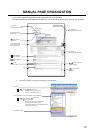
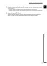
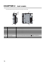
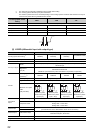
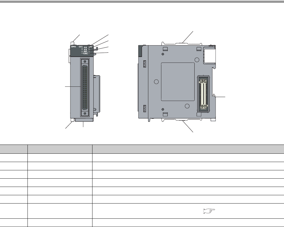
The following table lists the part names of the high-speed counter module.
No. Name Description
1) Module joint levers Levers for connecting two modules
2) A LED On: A voltage is being applied to the phase A pulse input terminal.
3) B LED On: A voltage is being applied to the phase B pulse input terminal.
4) DEC. LED On: Pulses are being counted down.
5) FUNC. LED On: A voltage is being applied to the function start input terminal.
6) DIN rail hook A hook used to mount the module to a DIN rail
7)
Connector for external
devices (40 pins)
A connector for I/O signal cables of external devices ( Page 41, Section 6.2.3)
8) Serial number display Displays the serial number printed on the rating plate.
1)
1)
2)
3)
4)
5)
1)
1)
6)
7)
8)