


38
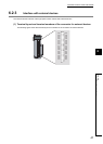
• Take the following noise reduction measures when wiring a connector for external devices.
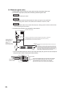
[Example of wiring using a shielded cable]
The following figure shows an example of wiring for noise reduction using the A6CON1.
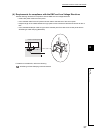
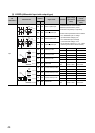
[Example of noise reduction measures taken to shielded cables]
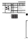
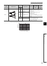
Assembling the A6CON1
From the controller
To the external device
Ground the shortest possible FG wire of 2mm
2
or more.
(Ground it to the panel on the high-speed counter module
side.)
From the encoder
Shielded
cable
Connector
(A6CON1)
To the high-speed counter module
The length between the connector
and shielded cables should be the
shortest possible.
Take off the jacket of each shield and connect
the shields of the cables with conductive tapes.
Cover the wires with
an insulating tape.
Take a shield out from any of the shielded cables,
and solder it to the FG wire.
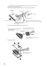
Coat the connector pins with heatshrinkable insulation
tubes to protect signal lines.
(Exposure of signal lines may cause malfunction
due to static electricity.)
Cover the wires and conductive tape
with a heatshrinkable tube.