


35
CHAPTER 6 INSTALLATION AND WIRING
6
6.2 Wiring
6.2.1 Wiring precautions
6.2 Wiring
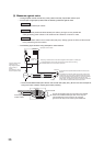
This section describes wiring of encoders and controllers to the high-speed counter module.
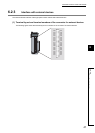
6.2.1 Wiring precautions
To obtain the maximum performance from the functions of the high-speed counter module and improve the system
reliability, an external wiring with high durability against noise is required.
Here are some precautions when wiring encoders and controllers.
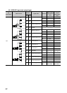
(1) Wiring
• Different terminals are prepared depending on the voltage of the signal to be input. Connecting to a terminal
with a different voltage may cause malfunction of the module or failure of the connected devices.
• In 1-phase input, always connect a pulse input cable on the A-phase side.
• Install a fuse for each external terminal to prevent the external devices or module from being burnt out or
damaged if a load shorts in an output circuit. The following fuses have been tested by Mitsubishi.
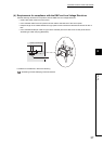
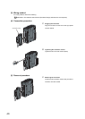
(2) Connectors for external devices
• Connectors for external devices must be soldered or crimped properly. A poor soldering or crimping may
result in malfunction.
• Securely connect the connectors for external devices to the connectors of the high-speed counter module,
and securely tighten the two screws.
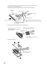
• When removing a cable from the high-speed counter module, do not pull the cable by the cable part.
Remove a cable supporting the connector part of the cable by hand. Pulling the cable being connected to the
high-speed counter module can cause malfunction. In addition, a damage of the high-speed counter module
or cables can result.
Fuse model name Rated current Contact
312.750 0.75A
Littlefuse KK
www.littelfuse.com
216.800 0.8A