


117
APPENDICES
A
Appendix 2 Details of Buffer Memory Areas
(7) CH Sampling/periodic counter flag (Un\G11, Un\G43)
• When the sampling counter function or the periodic pulse counter function is selected, the operating status of
the selected function is stored in this area.
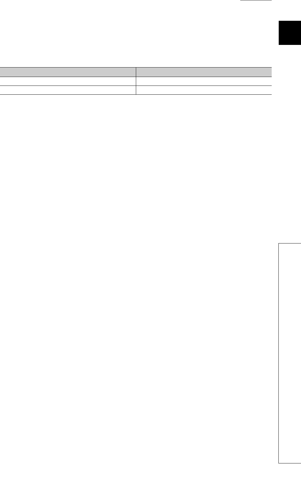
• Either of the following values is stored based on the operating status.
(8) CH Latch count value (Un\G12, Un\G13, Un\G44, Un\G45)
• The latch count value is stored in this area during execution of the latch counter function.
• The stored value ranges from -2147483648 to 2147483647 (32-bit signed binary).
(9) CH Sampling count value (Un\G14, Un\G15, Un\G46, Un\G47)
• The sampling count value is stored in this area during execution of the sampling counter function.
• The stored value ranges from -2147483648 to 2147483647 (32-bit signed binary).
(10)CH Periodic pulse count previous value (Un\G16, Un\G17, Un\G48, Un\G49),
CH Periodic pulse count present value (Un\G18, Un\G19, Un\G50, Un\G51)
• The previous and present periodic pulse count values are stored in this area during execution of the periodic
pulse counter function.
• The stored value ranges from -2147483648 to 2147483647 (32-bit signed binary).
(11)CH Ring counter lower limit (Un\G20, Un\G21, Un\52, Un\G53), CH Ring
counter upper limit (Un\G22, Un\G23, Un\G54, Un\G55)
• When the counter type is set to ring counter, the count range is stored in this area.
• The setting range is from -2147483648 to 2147483647 (32-bit signed binary).
Operating status Stored value
Function stopped 0
Function being performed 1