


36
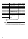
(3) Measures against noise
• The high-speed counter module may count pulses incorrectly if pulse-like noise is input.
• For the input of high-speed pulses, take the following measures against noise:
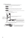
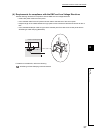
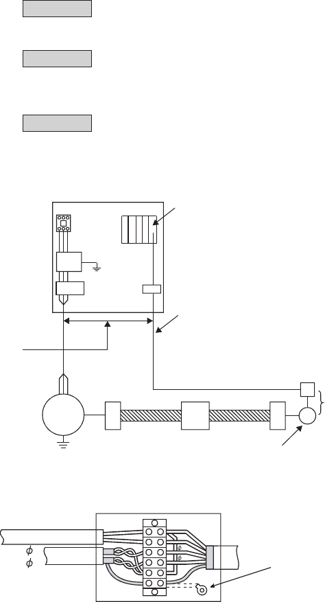
• The following figure shows a wiring example for noise reduction.
• Ground the shielded twisted pair cable on the encoder side (relay box). (Shown here is an example of
wiring to an open collector output type encoder (24VDC).)
Measure 1
Measure 2
Use shielded twisted pair cables.
Use the shortest possible shielded twisted pair cables, placing them not parallel with
noise-generating power cables or I/O cables and at a distance of 150mm or more.
Measure3
Ground the shield cable on the encoder side (relay box). Always ground the FG and LG terminals
to the protective ground conductor.
Avoid using a solenoid valve or inductive load together with the cable in a metallic pipe.
Install I/O cables at least
150mm away from
high voltage equipment
such as a relay or
inverter.
(Pay attention to wiring in
the control panel as well.)
Provide the shortest possible distance between the encoder and
relay box.
Terminal
block
Programmable
controller
AC motor
Relay box
Cart
Encoder
Inverter
Terminal
block
If a sufficient distance from the power line cannot be ensured due to duct wiring,
use shielded cables such as CVVS for the power line.
If the distance from the high-speed counter to the encoder is long,
a voltage drop may occur. Using a measuring instrument such as
a tester on the terminal block of the relay box, check if the voltages
in the encoder operation and stop status are within the rated
voltage range. If a voltage drop is too large, increase the cable size
or use a 24VDC encoder that will consume less current.
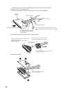
High-speed counter module
To A
To B
To the high-speed
counter module
Current for encoder
A
B
24V
E
+24V
0V
E
To the encoder
Connect the shielded cable of the encoder to the shielded
cable of the shielded twisted pair cable in the relay box.
If the shielded wire of the encoder is not grounded,
ground it to the relay box as shown by the dotted lines.