


97
CHAPTER 10 PROGRAMMING
10
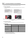
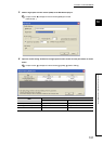
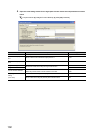
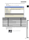
10.2 Connecting the Module to the Head Module
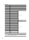
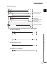
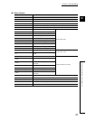
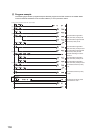
(4) User devices
Device Description
W1000 and W1001 Device to which the present value is to be written at auto refresh
W1002 and W1003 Device to which the latch count value is to be written at auto refresh
W1004 to W1005 Device to which the sampling count value is to be written at auto refresh
W1006 and W1007 Device to which the periodic pulse count previous value is to be written at auto refresh
W1008 and W1009 Device to which the periodic pulse count present value is to be written at auto refresh
W1010 Device to which the overflow status storage is to be written at auto refresh
X20 Count start signal
QX10 (X20 to X2F)
X22 Coincidence output data setting signal
X23 Preset command signal
X24 Count stop signal
X25 Coincidence LED clear signal
X26 Counter function start signal
X27 Counter function stop signal
X29 Latch execution signal
X2B Sampling count start signal
X2D Periodic pulse count start signal
Y30 Coincidence confirmation LED signal
QY10 (Y30 to Y3F)
Y31
Overflow occurrence confirmation LED
signal
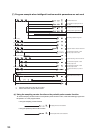
X1000 Module READY
LD62 (X/Y1000 to X/Y100F)
X1002
CH1 Counter value coincidence (point
No.1)
Y1000
CH1 Coincidence signal No.1 reset
command
Y1001 CH1 Preset command
Y1002 CH1 Coincidence signal enable command
Y1004 CH1 Count enable command
Y1006
CH1 Counter function selection start
command
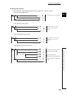
SB49 Data link status of the own station
SWB0.0 Data link status of each station (station No.1)
N0 Nesting (station No.1)
M0 Communication ready flag (station No.1)
T1 to T5 Interlock between the own and other stations