4 - 12 4 - 12
MELSEC-Q
4 SETTING AND PROCEDURE BEFORE OPERATION
[Module handling precautions]
• Since the module case is made of resin, do not drop it or subject it to strong
impacts.
• The module can be easily fixed onto the base unit using the hook at the top of
the module. However, it is recommended to secure the module with the
module fixing screw if the module is subject to significant vibration or shock. In
this case, tighten the module fixing screws within the following clamping torque
range.
Module fixing screws (M3): clamping torque ranging from 0.36 to 0.48 N•m
• Tighten the external power supply terminal screw of QJ71LP21S-25 within the
following torque range:
For the specification of the external power supply terminal, refer to section
3.1.1.
External power supply terminal screw (M3): torque ranging from 0.42 to 0.58
N•m
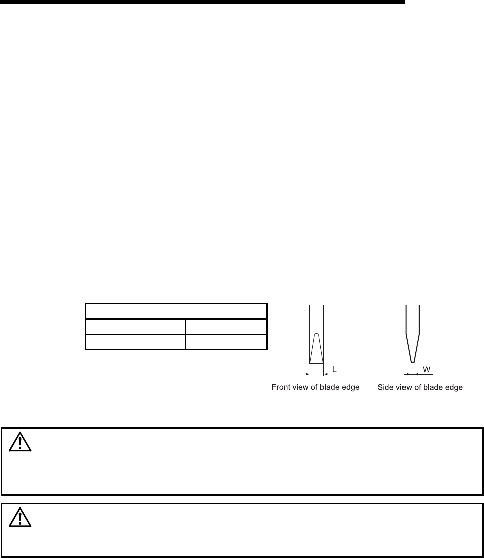
• Use drivers, which match the following recommended driver dimensions, for
the operation of the station number setting switch and the mode setting switch.
Using drivers with unsuitable edge width or thickness may damage the
switches.
Recommended driver dimensions
Edge width (L) 2.0 to 2.4mm
Edge thickness (W) 0.5 to 0.6mm
WARNING
Do not touch any terminal or connector while power is on.
Doing so will cause electric shock or malfunction.
Incorrect mounting or screwing may cause malfunction, failure, or drop of the
module. Overtightening can damage the screw and/or module, resulting in drop,
short circuit, or malfunction.
CAUTION
Prevent foreign matter such as dust or wire chips from entering the module. Such
foreign matter can cause a fire, failure, or malfunction.
Do not disassemble or modify the module.
Doing so may cause failure, malfunction, injury, or a fire.


