


11
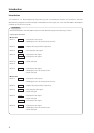
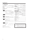
Controls and Connectors
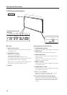
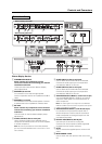
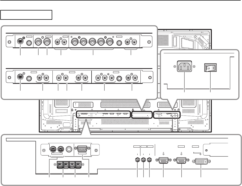
Connection Panel
Plasma Display Section
1 COMBINATION IN/OUT
Never connect any component to these
connectors without first consulting your Pioneer
installation technician.
These connectors are used for Plasma Display
setup adjustments.
2 SPEAKER (R) terminal
For connection of an external right speaker.
Connect a speaker that has an impedance of 6 Ω to
16 Ω.
3 SPEAKER (L) terminal
For connection of an external left speaker. Connect
a speaker that has an impedance of 6 Ω to 16 Ω.
4 RS-232C
Never connect any component to this connector
without first consulting your Pioneer installation
technician.
This connector is used for Plasma Display setup
adjustments.
5 AUDIO (OUTPUT) (Stereo mini jack)
Use to output the audio of the selected source
component connected to this unit to an AV amplifier
or similar component.
Note: No sound is produced from the AUDIO (OUTPUT)
jack when the MAIN POWER switch is set to OFF or when
set to Standby.
6 AUDIO (INPUT1) (Stereo mini jack)
Use to obtain sound when INPUT1 is selected.
Connect the audio output jack of components
connected to INPUT1 to this unit.
7 AUDIO (INPUT2) (Stereo mini jack)
Use to obtain sound when INPUT2 is selected.
Connect the audio output jack of components
connected to INPUT2 to this unit.
8 ANALOG RGB OUT (INPUT1) (mini D-sub 15 pin)
Use the ANALOG RGB OUT (INPUT1) terminal to
output the video signal to an external monitor or
other component.
Note: The video signal is not output from the ANALOG
RGB OUT (INPUT1) terminal when the panel's main power
is OFF or the panel is in Standby.
9 ANALOG RGB IN (INPUT1) (mini D-sub 15 pin)
For connection of a personal computer (PC) or
similar component. Confirm that the connection
made corresponds to the signal output from the
connected component.
0 DIGITAL RGB (INPUT2) (DVI-D jack)
Use this input to connect to a computer.
Connect to an AV component (HDCP supported)
equipped with DVI output connector.
- AC IN
Use to connect the supplied power cord to an AC
outlet.
= MAIN POWER switch
Use to switch the main power of the unit on and
off.
COMBINATION
IN OUT
RS-232C
AUDIO AUDIO
INPUT1
AUDIO
OUTPUT INPUT2
ANALOG RGB OUT
(D-Sub)
ANALOG RGB IN
(D-Sub)
INPUT1
DIGITAL RGB
(DVI-D)
INPUT2
S-VIDEO
S-VIDEO
OUT R L
RL R RLY Pb/Cb Pr/CrIN OUT
BR VD RLHD (H/V SYNC)G(ON SYNC)
INPUT3
INPUT3 INPUT4 INPUT5
VIDEO
INPUT4
INPUT 3/4 ANALOG RGB AUDIO
AUDIO
AUDIO AUDIO AUDIO
COMPONENT
VIDEO
VIDEO
INPUT5
IN
0432158967
=-
~
^
! @
* (
#
& ) _
%
+
$
L
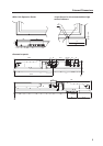
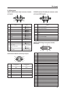
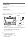
When installing PDA-5003
When installing PDA-5004