


125
Menu Mode[Applicable only when a PDA-5003/PDA-5004 is installed]
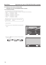
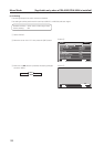
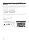
7) Color Decoding Setting
When a video signal is input at INPUT1, INPUT2 and INPUT5, it corresponds to an RGB and component video signal.
This setting must comply with the connected device.
The setting should be performed as shown below for INPUT1, INPUT2, and INPUT5.
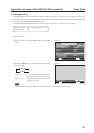
(Example)
• When reproducing an RGB signal: Set to ‘COLOR DECODING: RGB’.
• For reproduction from a DVD player: Set to ‘COLOR DECODING: COMPONENT1’.
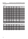
Settable condition: INPUT1, INPUT2, INPUT5
When a video signal (signal other than a PC signal) is input
Factory setting: For 525i, 525p, 625i, 625p signal input: COMPONENT1
For 750p, 1125i, 1125p, 1250p signal input: COMPONENT2
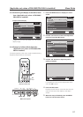
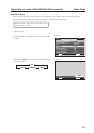
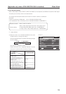
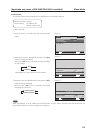
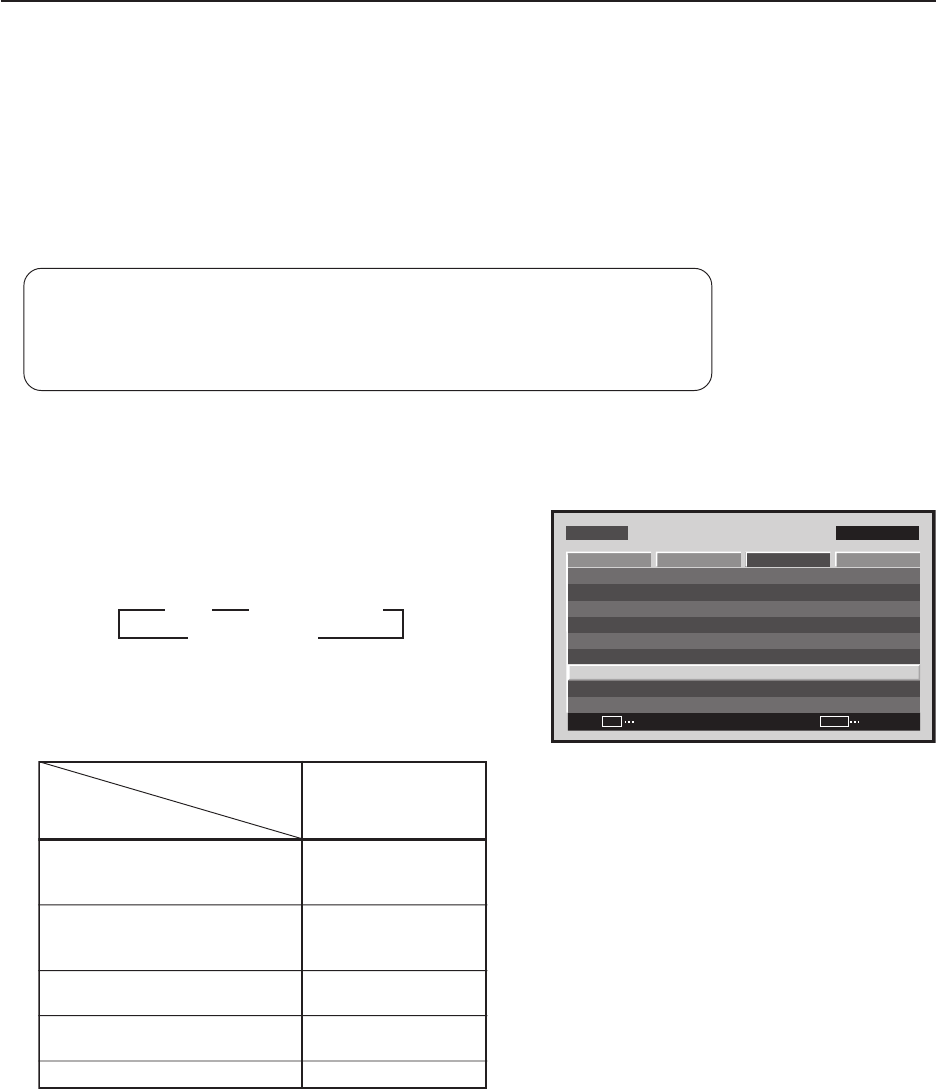
1 Select ‘SETUP’.
2 Place the cursor over ‘COLOR DECODING’ then press
the [SET] button to change the setting.
Each time the [SET] button is pressed, the setting changes
as shown below.
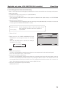
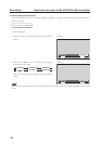
Set ‘COLOR DECODING‘ as follows.
Please take care when assigning settings. Incorrect
settings can adversely affect the Plasma Display.
MENU INPUT1
CHANGE
SET
EXIT
MENU
SCREEN SETUP OPTION
:DISABLE
:MIDDLE
COLOR TEMP. :MIDDLE
AUTO POWER OFF
DNR
:LOW
:ON
MPEG NR
CTI
:OFF
:RGB
PURECINEMA
COLOR DECODING
:AUTOCOLOR SYSTEM
SIGNAL FORMAT
PICTURE
Screen 2
3
RGB
COMPONENT22
3
COMPONENT1
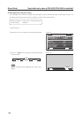
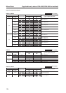
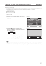
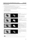
Component video output of
Y/Cb/Cr format.
For example, DVD player, etc.
Component video output of
Y/Pb/Pr format.
For example, digital tuner, etc.
RGB video output of a video deck
etc., with RGB output
DVI video output of an AV
component with DVI output port
RGB video output of a PC
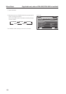
Connected
component
COLOR DECODING
SETUP
COMP.1
COMP.2
RGB
RGB
Not supported