


184
Integrator Mode
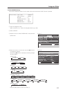
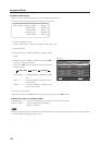
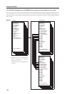
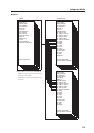
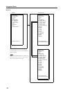
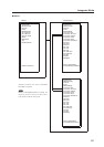
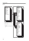
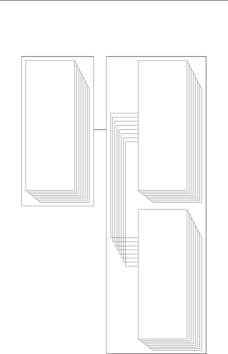
5.4.4 PICTURE, White Balance and SCREEN Position Adjustment Values Memory Area Tables
The memory areas for the PICTURE, White Balance and SCREEN adjustment values have the configuration shown
below. Adjustments in the menu mode share the same memory as the COLOR MODE NORMAL and STUDIO. The
adjustment values in the integrator mode are stored in memory that is separate from that for COLOR MODE NORMAL
and STUDIO.
7 INPUT1
¥CONTRAST
¥BRIGHTNESS
¥H. ENHANCE !
¥V. ENHANCE !
¥COLOR
★
¥TINT
★
¥SHARPNESS
★
¥H. POSITION
¥V. POSITION
¥CLOCK !
¥PHASE !
¥COLOR TEMP.
★
¥DNR
★
¥MPEG NR
★
¥CTI
★
¥PURECINEMA
★
¥COLOR DECODING
★
INPUT1–SIGNAL#1
¥CONTRAST
¥BRIGHTNESS
¥H. ENHANCE !
¥V. ENHANCE !
¥COLOR
★
¥TINT
★
¥SHARPNESS
★
¥C. DETAIL RED
¥C. DETAIL YELLOW
¥C. DETAIL GREEN
¥C. DETAIL CYAN
¥C. DETAIL BLUE
¥C. DETAIL MAGENTA
¥R. HIGH
¥G. HIGH
¥B. HIGH
¥R. LOW
¥G. LOW
¥B. LOW
¥H. POSITION
¥V. POSITION
¥CLOCK !
¥PHASE !
¥H. SIZE
¥V. SIZE
¥GAMMA
INPUT1–SIGNAL##A
(COLOR MODE; NORMAL)
¥CONTRAST
¥BRIGHTNESS
¥H. ENHANCE !
¥V. ENHANCE !
¥COLOR
★
¥TINT
★
¥SHARPNESS
★
¥C. DETAIL RED
¥C. DETAIL YELLOW
¥C. DETAIL GREEN
¥C. DETAIL CYAN
¥C. DETAIL BLUE
¥C. DETAIL MAGENTA
¥R. HIGH
¥G. HIGH
¥B. HIGH
¥R. LOW
¥G. LOW
¥B. LOW
¥H. POSITION
¥V. POSITION
¥CLOCK !
¥PHASE !
¥H. SIZE
¥V. SIZE
¥GAMMA
INPUT1–SIGNAL##A
(COLOR MODE; STUDIO)
MENU INTEGRATOR
★: Applicable only when a PDA-5003/PDA-
5004 is installed and when inputting/
adjusting a video signal.
! : Applicable only when inputting/adjusting a
PC signal.