


53
Video Card: PDA-5003/PDA-5004
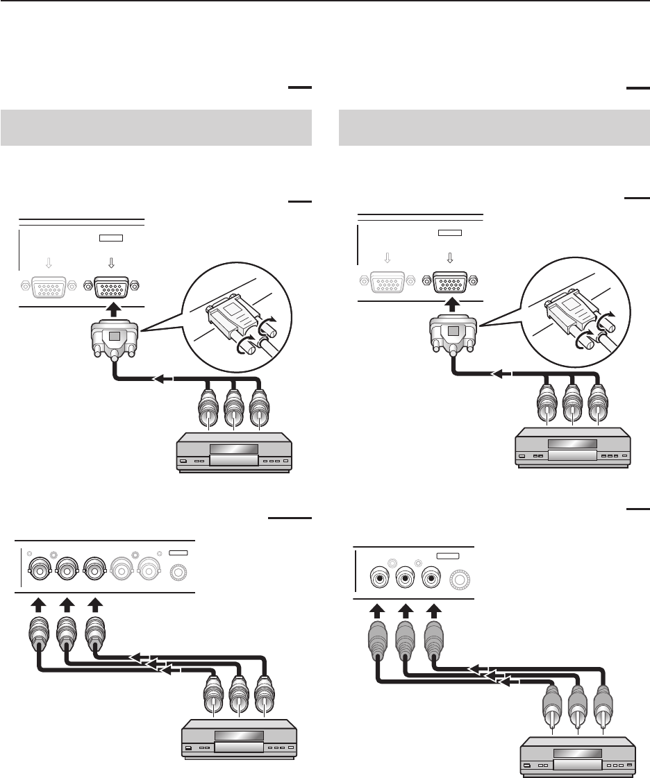
Connection to AV components
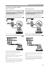
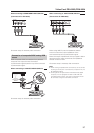
Connection to AV component equipped with
component video jacks
Make component video connections for AV
components equipped with component video jacks.
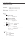
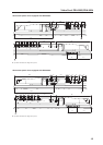
When connecting to ANALOG RGB IN (INPUT1)
ANALOG RGB OUT
(D-Sub)
ANALOG RGB IN
(D-Sub)
INPUT1
On-screen setup is necessary after connection.
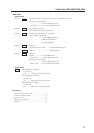
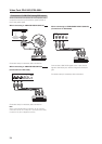
When connecting to ANALOG RGB (INPUT5)
BR VDHD (H/V SYNC)G(ON SYNC)
ANALOG RGB
INPUT5
Connect the Y signal to the G jack, the PB/CB signal to
the B jack, and the P
R/CR signal to the R jack.
On-screen setup is necessary after connection.
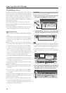
INPUT5 jacks are all BNC jacks.
If necessary, use commercially available BNC/pin-plug
conversion adapters to make connections.
Note
The Plasma Display and this Video Card are designed to
support component video signals with standard, stable signal
levels and sync signals. As a result, some image disruption
may be generated during use of various special trick play
functions on video components.
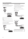
4.3.6 Connection to INPUT1 or INPUT5
7 When using PDA-5003
Connection to AV components
Connection to AV component equipped with
component video jacks
Make component video connections for AV
components equipped with component video jacks.
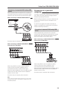
When connecting to ANALOG RGB IN (INPUT1)
ANALOG RGB OUT
(D-Sub)
ANALOG RGB IN
(D-Sub)
INPUT1
On-screen setup is necessary after connection.
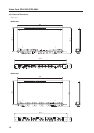
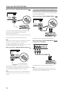
When connecting to COMPONENT VIDEO (INPUT5)
Y Pb/Cb Pr/Cr
INPUT5
COMPONENT
VIDEO
Connect the Y signal to the Y jack, the PB/CB signal to
the P
B/CB jack, and the PR/CR signal to the PR/CR jack.
Note
The Plasma Display and this Video Card are designed to
support component video signals with standard, stable signal
levels and sync signals. As a result, some image disruption
may be generated during use of various special trick play
functions on video components.
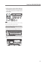
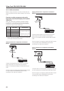
7 When using PDA-5004