


54
Video Card: PDA-5003/PDA-5004
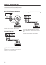
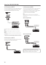
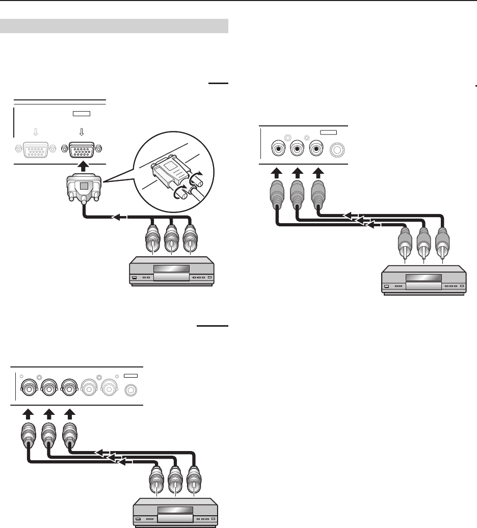
Connection of G ON SYNC analog RGB source
Make G ON SYNC connections for a component with
output that has the synchronization signal layered on
top of the green signal.
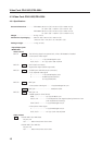
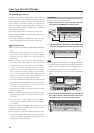
When connecting to ANALOG RGB IN (INPUT1)
ANALOG RGB OUT
(D-Sub)
ANALOG RGB IN
(D-Sub)
INPUT1
On-screen setup is necessary after connection.
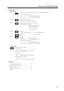
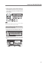
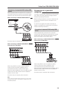
When connecting to ANALOG RGB (INPUT5)
[Connections for PDA-5003]
BR VDHD (H/V SYNC)G(ON SYNC)
ANALOG RGB
INPUT5
On-screen setup is necessary after connection.
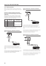
Note
When making G ON SYNC connections, do not make any
connections to the VD or HD jacks. If connections are made,
the picture may be not displayed normally.
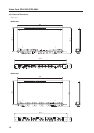
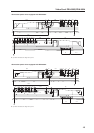
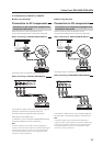
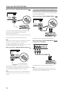
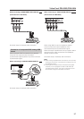
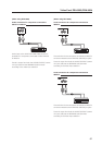
When connecting to COMPONENT VIDEO (INPUT5)
[Connections for PDA-5004]
Y Pb/Cb Pr/Cr
INPUT5
COMPONENT
VIDEO
Connect the G ON SYNC signal to the Y jack, the B
signal to the P
B/CB jack, and the R signal to the PR/CR
jack.
On-screen setup is necessary after connection.