


52
Video Card: PDA-5003/PDA-5004
*1 Although INPUT1 and INPUT5 are compatible with various
kinds of signals, setup using the on-screen menu is
necessary after connections are made in order match the
characteristics of the source component.
*2 INPUT1 is compatible with Microsoft’s Plug & Play (VESA
DDC 1/2B).
*3 Depending on the video output board of the computer, this
type of connection may not be possible.
*4 INPUT2 is compatible with Microsoft’s Plug & Play (VESA
DDC 2B).
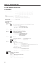
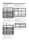
Analog RGB
S video
Composite video
Digital RGB
Input
Connector
INPUT
1
*1
INPUT
2
INPUT
4
INPUT
3
Analog RGB
Component video
S video
Composite video
Digital RGB
Personal computer
(PC)
AV component
Connected
component
and signals
INPUT
5
*1
*2
*3
*3
*4
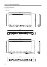
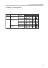
7 When using PDA-5004
Consult the following chart when making connections to
a Plasma Display equipped with this video card.
4.3.4 Input connectors on the Plasma Display
with video card
7 When using PDA-5003
Consult the following chart when making connections to
a Plasma Display equipped with this video card.
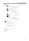
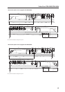
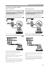
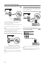
4.3.5 Connection to INPUT1 and INPUT5
7 When using PDA-5003
Various components can be connected to the INPUT1 and
INPUT5 jacks. After connections are made, on-screen
setup is necessary to match the characteristics of the
connected component.
Input
Connector
INPUT
1
*1
INPUT
2
INPUT
4
INPUT
3
Analog RGB
Component video
S video
Composite video
Digital RGB
Personal computer
(PC)
AV component
Connected
component
and signals
INPUT
5
*1
Analog RGB
S video
Composite video
Digital RGB
*2
*3
*3
*4
: Do not connect anything. : Connect to this jack.
Note
Components compatible with INPUT1 are also compatible with
INPUT5. When making connections to INPUT1, please refer to
the Plasma Display’s Operating Instructions.
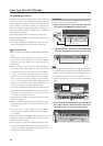
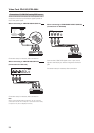
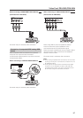
7 When using PDA-5004
Various components can be connected to the INPUT1 and
INPUT5 jack. After connections are made, on-screen setup
is necessary to match the characteristics of the connected
component.
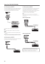
INPUT5 jack
Y
Output source
Video component/personal
computer (PC) with RGB
output
G ON SYNC
Video component with
component video output
Y
PB/CB
B
PB/CB
PR/CR
R
PR/CR
: Connect to this jack.
Note
When making connections to INPUT1, please refer to the
Plasma Display’s Operating Instructions.
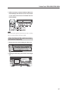
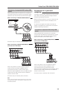
INPUT5
jack
Output source
[ON SYNC]
GBR
[H/V SYNC]
HD VD
Video component/
personal
computer (PC)
with RGB output
G ON SYNC
R
RG
GBR
B
B
VD
H/V SYNC
HD
Video component
with component
video output
Y PB/CB PR/CR