


20
Installation Conditions
3.2.4 Mounting surface warping
The display incorporates glass. Before mounting the panel using hardware other than that provided by Pioneer, perform
the following checks to confirm that the display is free from warps exceeding 1 mm*.
Regarding the 1 mm limit:
The panel frame may have a warp of up to 3 mm. If the total warp (the warp of the frame plus the warp of the
mounting surface) exceeds 4 mm then the glass in the display may experience excessive stress. To ensure that
the total warp is less than 4 mm, verify that the warp of the mounting surface is less than 1 mm.
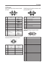
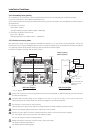
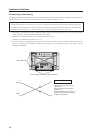
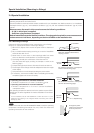
1 Referring to the illustration below, diagonally extend string (maximum diameter
φ
0.1- mm) through the bolt
mount openings. Strings should be completely free of slack.
2 Measure the clearance (L) between the strings where they cross.
Distortion is expressed by: [Distortion] = L × 2.
3 If L is found to be 0, pass the strings through the other bolt mount openings then repeat the measurements. Any
value of L greater than 0 indicates the presence of distortion. If the measured value in both cases is 0, the
distortion is negligible.
A
B
D
F
E
C
Mount bolt holes
Plasma Display Mount Surface (Mount Brackets)
String
String
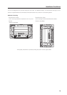
Magnified view of section A
Point E is the center point of string
segment A-B.
Point F is the center point of string
segment C-D.
Clearance between points E and F = L
(Points E and F are shown displaced
for illustrative purposes).
A