


12
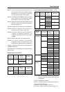
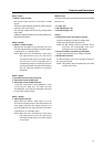
2.3 Controls and Connectors
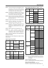
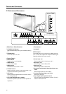
Controls and Connectors
C. VIDEO
GBRHDVD
INPUT 4 OUTPUT
(INPUT 4)
75Ω 2.2kΩ
YCB/PB
INPUT 3(ON SYNC) (H/V SYNC)
C
R/PR
INPUT 1
INPUT 2 CONBINATION
RS - 232C
CONTROL
OUTPUT
(INPUT 1)
Y
IN OUT IN OUT
S - VIDEO VIDEO C
B/PB CR/PR
Î
POWER
STANDBY
/ON
INPUT
MENU
ADJUST
SET
3
4
5
6
7
9 0 ! @ # $
21
% ^ & * ( ) _
~=-
8
+ ™¡
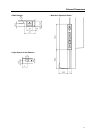
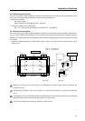
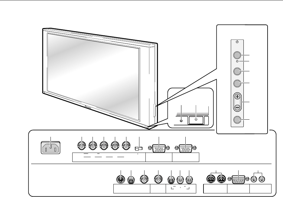
< Operation Panel >
< Connectors >
(at the rear of the main unit)
< Main Power Switch Section >
1 STANDBY/ON indicator
Red indicates standby status, green indicates powering
on.
2 POWER switch
Turns main power on or off.
< Control Panel >
3 Power switch
Toggles unit on or off (standby).
4 INPUT switch
Used to select inputs
5 MENU switch
Switches the menu screen on or off.
6 ADJUST buttons
Used to move the cursor on the menu screen or to
increment/decrement adjustment values
7 SET button
Used to select an adjustment item in the menu screen
or to change settings
8 KEY LOCK/UNLOCK button (hidden)
Renders the operation panel and remote operative or
inoperative.
< Connectors >
9 AC INLET
INPUT 3 Inputs
These RGB inputs are composed of five BNC terminals,
0 to !. They also support the component video signal
(settings required in the menu screen).
0 Green Input: 75Ω
Receives signals of G, G with sync, and Y.
- Blue Input: 75Ω
Receives signals of B, CB, and PB.
= Red Input: 75Ω
Receives signals of R, CR, and PR.
~ Horizontal and Composite Sync Signal Input: 75Ω/
2.2kΩ
Receives signals of HD, and H/V Sync.
! Vertical Sync Signal Input: 75Ω/2.2 kΩ
Receives a VD signal.
@ Sync Signal Input Impedance switch
Used to switch input impedance for items ~ and !
between 75Ω and 2.2 kΩ.