67
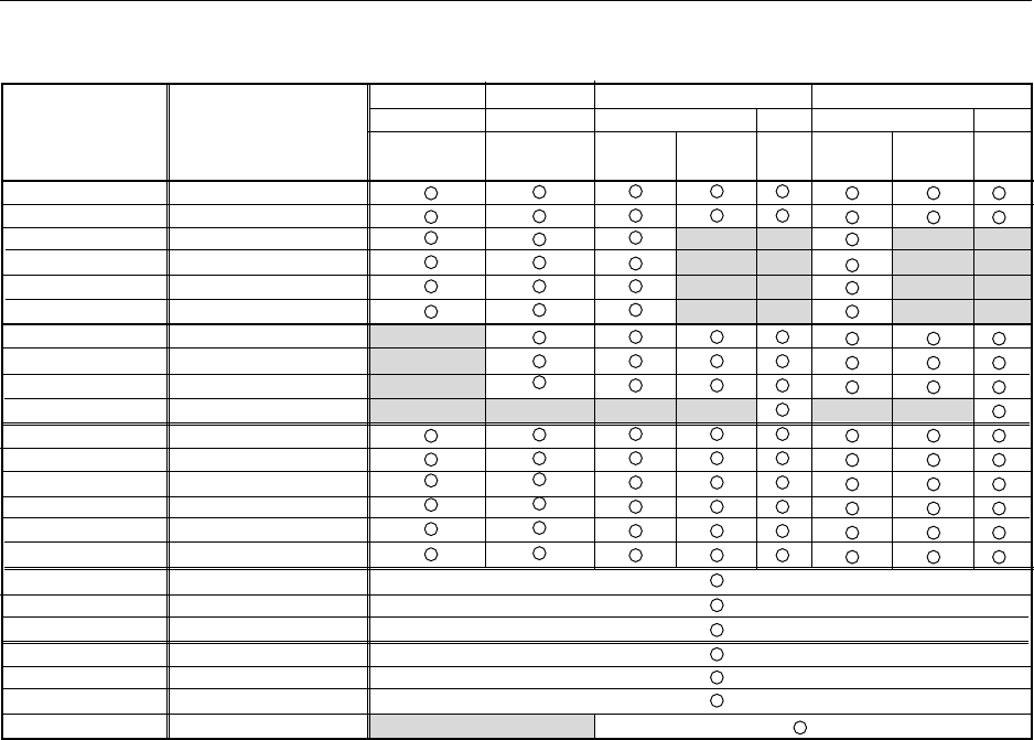
Before Beginning Adjustments
CONTRAST
BRIGHT
COLOUR
TINT
SHARP
DETAIL
H. POSITION
V. POSITION
CLK FREQ.
CLK PHASE
R HIGH
G HIGH
B HIGH
R LOW
G LOW
B LOW
SIDE MASK R
SIDE MASK G
SIDE MASK B
COLOUR MODE
BAUD RATE
MIRROR MODE
STD-RGB
0 to (128) to 255
0 to (128) to 255
0 to (64) to 127
0 to (64) to 127
0 to (128) to 255
0 to (128) to 255
0 to (128) to 255 Note 1
0 to (128) to 255 Note 1
64 to (128) to 192
0 to (8) to 16
0 to (128) to 255
0 to (128) to 255
0 to (128) to 255
0 to (128) to 255
0 to (128) to 255
0 to (128) to 255
0 to (128) to 255
0 to (128) to 255
0 to (128) to 255
1/2
1200 to 19200 Note 2
OFF/XY
OFF/ON
Variable Range
Median Value in
Parentheses
Adjustment
INPUT 4
VIDEO PC
COMPO- RGB RGB
NENT
INPUT 3
VIDEO PC
COMPO- RGB RGB
NENT
INPUT 1
VIDEO
COMPOSITE
/S-Video
INPUT 2
VIDEO
COMPO-
NENT
2) Integrator Mode
Note 1: The one-step increment may vary, depending on input signal and screen size. The range of adjustment values
is also bounded (a limiter is inserted).
Note 2: Switchable in five steps.
* For RS-232C adjustment mode, refer to “5.3.3 List of RS-232C Commands.”


