M102E/M501 TRS GETTING STARTED
(Addendum to M101E Manual - P/N 04740 Rev A)
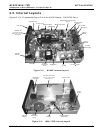
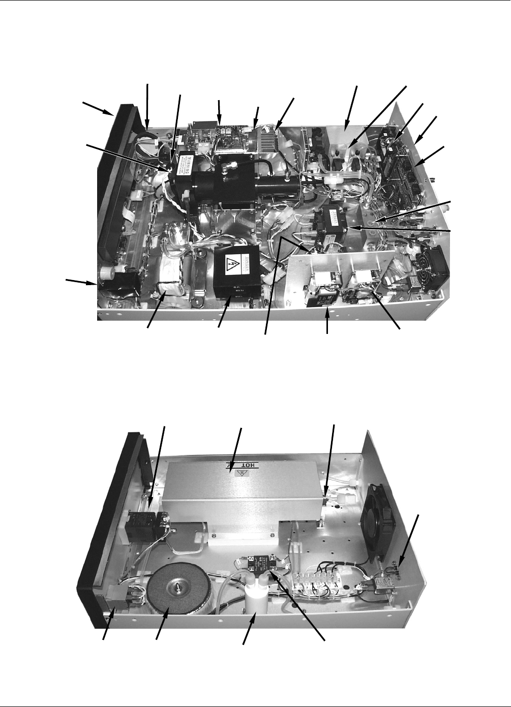
3.3. Internal Layouts
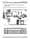
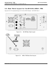
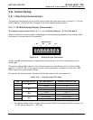
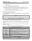
Figures 3-1 & 3-3 supersede Figure 3-9 of the M101E Manual - P/N 04740 Rev A.
Front Panel
UV Source La
p
Particulate Filter
Reaction Cell
Hydrocarbon Scrubber
Hidden from view beneath
Reaction Cell
PMT Housin
g
PMT Pream
p
PCA
PMT Coolin
g
S
y
stem
Rear Panel
PC
/
104 Card
Span/Cal Valves
(Option)
Vacuum
Manifold
Mother
Board
ON/OFF
SWITCH
PS1
(+5 VDC; ±15VDC)
PS2
(+12 VDC)
Pum
p
Ass
y
Rela
y
Board
230VAC
Transformer
(Option)
UV Lamp
Power Supply
IZS Permeation Tube and Oven
(Option)
Figure 3-1: M102E Internal Layout
Converter Tube
Converter Tube Cover
Converter Heater located
underneath Cover
Temperature
Controller
ON/OFF
SWITCH
230VAC
Transformer
(Option)
SO
2
Scrubber
Converter Heater
Control Relay
Alarm
Outputs
Figure 3-2: M501-TRS Internal Layout
05514 Rev A1 7


