


GETTING STARTED M102E/M501 TRS
(Addendum to M101E Manual - P/N 04740 Rev A)
3.6. Initial Setup
3.6.1. Electrical Connections:
The electrical connections for the M102E are the same as those described in Section 3.1.1 of the
M101E Manual - P/N 04740 Rev A except for the test channel analog output:
3.6.1.1. M102E Analog Output Connections
This section supercedes Section 3.1.1.1 of the M101E Manual - P/N 04740 Rev A.
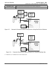
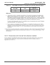
Attach a strip chart recorder and/or data-logger to the appropriate contacts of the analog output
connecter on the rear panel of the analyzer.
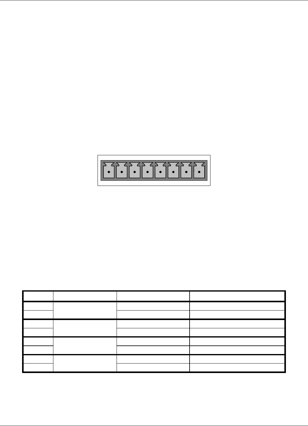
ANALOG OUT
A1 A2 A3 A4
+ - + - + - + -
Figure 3-6: Analog Output Connector
The A1 and A2 channels output a signal that is proportional to the SO
2
concentration of the
sample gas.
The output, labeled A3 is special. It can be set by the user (see Section 6.9.10 of the M101E
Manual - P/N 04740 Rev A) to output any one of the parameters accessible through the <TST
TST> keys of the units sample display.
Pin-outs for the Analog Output connector at the rear panel of the instrument are:
Table 3–2: Analog output Pin Outs
PIN ANALOG OUTPUT VOLTAGE OUTPUT CURRENT LOOP OPTION
1 V Out I Out +
2
A1
Ground I Out -
3 V Out I Out +
4
A2
Ground I Out -
5 V Out I Out +
6
A3
Ground I Out -
7 Not Available Not Available
8
A4
Not Available Not Available
• The default analog output voltage setting of the M102E UV Fluorescence SO
2
Analyzer is 0
– 5 VDC with a range of 0 – 500 ppb.
10 05514 Rev A1