


M102E/M501 TRS PREFACE
(Addendum to M101E Manual - P/N 04740 Rev A)
LIST OF FIGURES
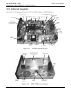
Figure 3-1: M102E Internal Layout ...................................................................................7
Figure 3-2: M501-TRS Internal Layout...............................................................................7
Figure 3-3: Internal Pneumatic Diagram of the M102E Standard Configuration........................8
Figure 3-4: M102E Rear Panel Layout................................................................................9
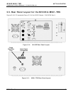
Figure 3-5: M501-TRS Rear Panel Layout...........................................................................9
Figure 3-6: Analog Output Connector .............................................................................. 10
Figure 3-7: Pneumatic Connections–Basic Configuration–Using Gas Dilution Calibrator ........... 12
Figure 3-8: Pneumatic Connections–Basic Configuration–Using Bottled Span Gas .................. 12
Figure 3-9: Basic Pneumatic Connections for Units with Zero/Span Valve Option ................... 15
Figure 3-10: Pneumatic Connections for Formal Calibration of Units with an IZS Valve Option ... 16
Figure 3-11: Pneumatic Connections for Informal Calibration Checks of Units with IZS Valve
Option ...................................................................................................... 16
Figure 3-12: M501-TRS Temperature Controller Startup ..................................................... 18
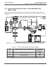
Figure 4-1: Internal Pneumatic Diagram of the M102E With Z/S Option Installed................... 22
Figure 4-2: Internal Pneumatic Diagram of the M102E with IZS Options Installed. ................. 23
Figure 5-1: Analog Output Connector Key........................................................................ 25
Figure 5-2: Control Inputs with local 5 V power supply ...................................................... 28
Figure 5-3: Control Inputs with external 5 V power supply ................................................. 29
Figure 6–1: M501-TRS Temperature Controls ................................................................... 31
Figure 9-1: UV Absorption in the M102E Reaction Cell ....................................................... 44
Figure 9-2: M102E Sensor Module .................................................................................. 47
Figure 9-3: M102E Sample Chamber............................................................................... 48
Figure 9-4: M501-TRS Electronic Block Diagram ............................................................... 49
Figure 10-1: Shutter Assembly - Exploded View.................................................................. 57
Figure 10-2: Disassembling the Shutter Assembly............................................................... 58
Figure 10-3: PMT Assembly - Exploded View ...................................................................... 59
Figure 10-4: Pre-Amplifier Board Layout............................................................................ 62
LIST OF TABLES
Table 2-1: Model 102E Basic Unit Specifications..................................................................3
Table 3-1: TRS – SO
2
Switching Valve Operating Modes.......................................................8
Table 3–2: Analog output Pin Outs................................................................................... 10
Table 3-3: Inlet / Outlet Connector Nomenclature............................................................. 11
Table 3-4: NIST-SRM's Available for Traceability of H
2
S & SO
2
Calibration Gases .................... 14
Table 4-1: Zero/Span Valve Operating States.................................................................. 22
Table 4-2: IZS Valve Operating States ........................................................................... 23
Table 5-1 M102E gas Measurement Modes...................................................................... 26
Table 5-2: Analog Output Pin Assignments....................................................................... 26
Table 5-3: Test Parameters Available for Analog Output A4 ................................................ 27
Table 5-4: M102E Control Input Pin Assignments .............................................................. 28
Table 5-5: M102E Default Hessen Gas ID’s....................................................................... 29
Table 5-6: Default Hessen Status Bit Assignments ............................................................ 30
Table 6-1: M501-TRS Temperature Controls and Definitions ............................................... 32
Table 8-1: M102E Preventive Maintenance Schedule.......................................................... 39
Table 10-1: Test Functions - Possible Causes for Out-Of-Range Values ................................... 51
Table 10-2: Test Functions - Possible Causes for Out-Of-Range Values ................................... 52
Table 10-3 – Temperature Controller – Primary Parameter Settings......................................... 66
Table 10-4 – Temperature Controller – Primary Parameter Settings......................................... 67
05514 Rev A1 iii