


M102E/M501 TRS GETTING STARTED
(Addendum to M101E Manual - P/N 04740 Rev A)
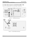
3.7. Initial Operation
3.7.1. Startup / Warm Up of the M102E
Startup procedures and warm up behavior of the M102E are identical to those described in
Sections 3.2.1 and 3.2.2 of the M101E Manual - P/N 04740 Rev A.
Possible Warning Messages at Start-Up
Warning messages for the M102E is the same as the list of warning messages included in
appendix A—3 of the M101E Manual - P/N 04740 Rev A with the exception that there is no CONV
TEMP WARNING (converter Temperature Warning).
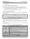
3.7.2. Functional Check of the M102E
To performing an initial functional check of the M102E follow the steps contained in Section 3.2.4
of the M101E Manual - P/N 04740 Rev A.
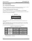
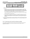
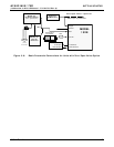
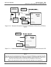
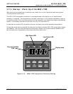
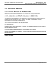
Test Functions
The following diagram supercedes the one found in Step 2 of Section 3.2.4 of the M101E Manual -
P/N 04740 Rev A.
1
Only appears if IZS option is
installed.
2
Only appears if analog output A4
is actively reporting a test function.
3
Shown as they appear when analyzer
is in TRS mode. In SO
2
mode appear as SO2 STB, SO2 OFFS &
SO2 SLOPE. In multigas mode, both versions appear.
RANGE
TRS STB
3
PRES
SAMP FL
PMT
NORM PMT
UV LAMP
LAMP RATIO
STR. LGT
DARK PMT
DARK LAMP
TRS SLOPE
3
TRS OFFS
3
HVPS
RCELL TEMP
BOX TEMP
PMT TEMP
IZS TEMP
1
TEST
2
TIME
SAMPLE RANGE = 500.0 PPB TRS = X.X
< TST TST > CAL SETUP
Refer to Section
6.2.1 of the M101E
Manual - P/N 04740
Rev A for definitions
of these test
functions.
Toggle <TST TST> keys to
scroll throu
g
h list of functions
05514 Rev A1 17