


THEORY OF OPERATION M102E/M501 TRS
(Addendum to M101E Manual - P/N 04740 Rev A)
9.2. The UV Light Path
The following information is in addition to that contained in Section 10.2 of the M101E Manual -
P/N 04740 Rev A.
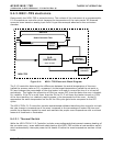
9.2.1. UV Lamp Shutter & PMT Offset
Inherent in the operation of both the reference detector and the PMT are minor electronic offsets.
The degree of offset differs from detector to detector and from PMT to PMT and can change over
time as these components age.
To account for these offsets the M102E includes a shutter, located between the UV Lamp and the
source filter, that periodically cuts off the UV light from the sample chamber. This happens every
30 minutes. The analyzer records the outputs of both the reference detector and the PMT during
this dark period and factors them into the SO
2
concentration calculation.
• The reference detector offset is stored as and viewable via the front panel as the test
function DRK LMP.
• The PMT offset is stored as and viewable via the front panel as the test function DRK PMT
9.3. Pneumatic Operation
9.3.1. Sample gas Flow
See Figures 3-4. 4-1 and 4-2 for depictions of the internal pneumatic flow of both the M102E &
the M501-TRS.
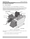
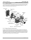
9.3.2. M501 SO
2
Scrubber
In order to ensure that no ambient SO
2
interferes with the analyzer’s TRS measurement the
sample gas stream is passed through a chemical scrubber that removes SO
2
from the sample
stream before it is passed though the M501-TRS converter oven.
The SO
2
scrubber is a Teflon encased, stand-alone unit containing a room-temperature catalyst
tube mounted in the right side of the converter case (see Figure 3.2).
The SO
2
scrubber material is consumed as it removes SO
2
. If the expected concentrations of SO
2
are very high, the lifetime of the scrubber will be short. The expected life of the scrubber is
approximately 1000 ppm-hours. See Section 8.1.1.3 for information on when and how to replace
the SO
2
scrubber material)
46 05514 Rev A1