M102E OPERATING INSTRUCTIONS M102E/M501 TRS
(Addendum to M101E Manual - P/N 04740 Rev A)
5.4. Remote Operation of the Analyzer
5.4.1. Control Inputs
The description of the control inputs in Section 6.12.1.2 of the M101E Manual - P/N 04740 Rev A
in correctly shows an external low span cal input. This is not correct. Neither the M102E nor the
M102E has an external low span cal input.
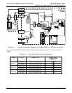
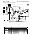
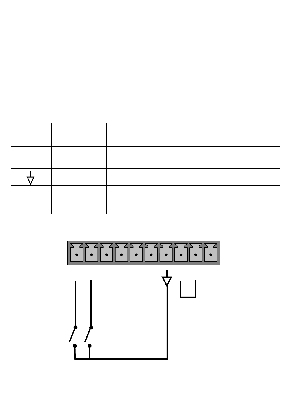
The following table and figures supercede Table 6-23 and Figures 6-18 & 6-19 of the M101E
Manual - P/N 04740 Rev A respectively.
Table 5-4: M102E Control Input Pin Assignments
INPUT STATUS CONDITION WHEN ENABLED
A External Zero Cal
Zero calibration mode is activated. The mode field of the
display will read ZERO CAL R.
B External Span Cal
Span calibration mode is activated. The mode field of the
display will read SPAN CAL R.
C, D, E, & F Unused
Digital Ground Provided to ground an external device (e.g., recorder).
U
DC Power For
Input Pull Ups
Input for +5 VDC required to activate inputs A - F. This voltage
can be taken from an external source or from the “+” pin.
+
Internal +5v
Supply
Internal source of +5V which can be used to activate inputs
when connected to pin U.
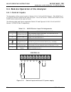
CONTROL IN
A B C D E F U
+
SPAN
ZERO
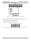
Figure 5-2: Control Inputs with local 5 V power supply
28 05514 Rev A1


