


THEORY OF OPERATION M102E/M501 TRS
(Addendum to M101E Manual - P/N 04740 Rev A)
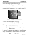
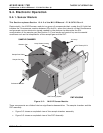
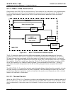
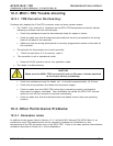
9.4.1.1. Sample Chamber
The main electronic components of the sample chamber are the reference detector(see Section
10.2.2 of the M101E Manual - P/N 04740 Rev A); the UV Lamp (see Section 10.2.1 of the M101E
Manual - P/N 04740 Rev A) and its electronically operated shutter (see Section 9.2.1 of this
addendum); and the sample chamber heating circuit,
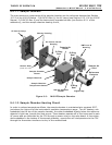
UV Source Lamp
Shutter Housing
Shutter Assy
(hidden from view)
UV Source Lens &
Housing
PMT Lens &
Housing
Sample Chamber
Sample Chamber
Heater
Sample Chamber
Temperature Sensor
Reference
Detector
Li
g
ht Trap
Sample Air
Outlet
O-Ring
Seal
Sample Air
Inlet
Sample Chamber
Heater
O-Ring
Seal
O-Ring
Seal
Figure 9-3: M102E Sample Chamber
9.4.1.2. Sample Chamber Heating Circuit
In order to reduce temperature effects, the sample chamber is maintained at a constant 50°C,
just above the high end of the instrument’s operation temperature range. Two AC heaters, one
embedded into the top of the sample chamber, the other embedded directly below the reference
detector’s light trap, provide the heat source. These heaters operate off of the instrument’s main
AC power and are controlled by the CPU through a power relay on the relay board. A thermistor,
also embedded in the bottom of the sample chamber, reports the cell’s temperature to the CPU
through the thermistor interface circuitry of the motherboard.
48 05514 Rev A1