


M102E/M501 TRS
(Addendum to M101E Manual - P/N 04740 Rev A)
TABLE OF CONTENTS
1. PREFACE ...................................................................................................................................... 1
1.1. Reference Numbering convention...............................................................................................2
2. SPECIFICATIONS, APPROVALS AND WARRANTY.......................................................................... 3
2.1. Specifications..........................................................................................................................3
2.1.1. M501-TRS Specifications ....................................................................................................3
2.2. EPA Equivalency Designation.....................................................................................................3
2.3. CE Mark Compliance ................................................................................................................4
3. GETTING STARTED....................................................................................................................... 5
3.1. Unpacking the M102E ..............................................................................................................5
3.2. Unpacking the M501-TRS .........................................................................................................5
3.2.1. M501-TRS Ventilation Clearance: ........................................................................................6
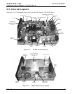
3.3. Internal Layouts......................................................................................................................7
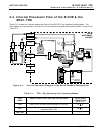
3.4. Internal Pneumatic Flow of the M102E & the M501-TRS ................................................................8
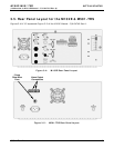
3.5. Rear Panel Layout for the M102E & M501-TRS .............................................................................9
3.6. Initial Setup .........................................................................................................................10
3.6.1. Electrical Connections:.....................................................................................................10
3.6.1.1. M102E Analog Output Connections..............................................................................10
3.6.1.2. M501-TRS Alarm Output Connections ..........................................................................11
3.6.2. Pneumatic Connections:...................................................................................................11
3.6.2.1. Connections with Internal Valve Options Installed..........................................................14
3.7. Initial Operation....................................................................................................................17
3.7.1. Startup / Warm Up of the M102E.......................................................................................17
3.7.2. Functional Check of the M102E..........................................................................................17
3.7.3. Startup / Warm Up of the M501-TRS..................................................................................18
3.8. Initial Calibration...................................................................................................................19
4. OPTIONAL HARDWARE AND SOFTWARE .................................................................................... 21
4.1. Rack Mount Kits (Options 20a, 20b, 21, 22 & 81).......................................................................21
4.2. Calibration Valves Options ......................................................................................................21
4.2.1. Zero/Span Valves (Option 50) & Internal Zero/Span Gas Generator (Option 51).......................21
4.3. Additional Manuals.................................................................................................................24
4.3.1. Printed Manuals (P/N 049880000) .....................................................................................24
4.3.2. Addendum on CD (Part number 049880200).......................................................................24
5. M102E OPERATING INSTRUCTIONS........................................................................................... 25
5.1.1. M102E Analog Output Signals ...........................................................................................25
5.1.2. Setting the M102E Gas Measurement Mode.........................................................................26
5.2. SETUP – DIAG: Using the Diagnostics Functions.........................................................................26
5.2.1. M102E Analog I/O Configuration........................................................................................26
5.2.2. M102E Test Channel Output .............................................................................................27
5.3. SETUP – COMM: Setting Up the M102E’s Communication Ports ....................................................27
5.3.1. M102E ID Code...............................................................................................................27
5.3.2. M102E Ethernet Host Name..............................................................................................27
5.4. Remote Operation of the Analyzer............................................................................................28
5.4.1. Control Inputs ................................................................................................................28
5.4.2. Using the M102E with a Hessen Protocol Network ................................................................29
5.4.2.1. M102E Hessen Protocol Gas ID List. ............................................................................29
5.4.2.2. Setting Hessen Protocol Status Flags ...........................................................................30
6. M501-TRS OPERATING INSTRUCTIONS ..................................................................................... 31
6.1. Basic M501-TRS Controls........................................................................................................31
6.2. To Display The Current Temperature:.......................................................................................32
6.3. To Manually Adjust the Converter Oven Temperature: ................................................................33
6.4. Autotune the Temperature Controller: ......................................................................................34
6.4.1. Initiating the Autotune Process: ........................................................................................34
6.4.2. Aborting the Autotune Process:.........................................................................................35
6.5. M501TRS Alarm Relay Adjustment ...........................................................................................35
7. CALIBRATION PROCEDURES ...................................................................................................... 37
7.1. M102E Calibration .................................................................................................................37
7.2. M501-TRS Calibration ............................................................................................................37
05514 Rev A1 i