


APPENDIX A-4: M102E Signal I/O Definitions, Revision A.2 M102E/M501 TRS
(Addendum to M101E Manual - P/N 04740 Rev A)
APPENDIX A-4: M102E Signal I/O Definitions, Revision A.2
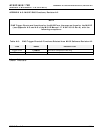
NOTE
Signal I/O Definitions for the M102E are the same as those for the M102E (see
Appendix A-4 of the M101E Manual - P/N 04740110 Rev A) with the following
exceptions:
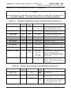
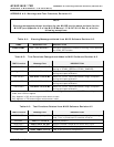
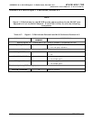
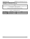
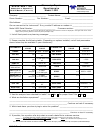
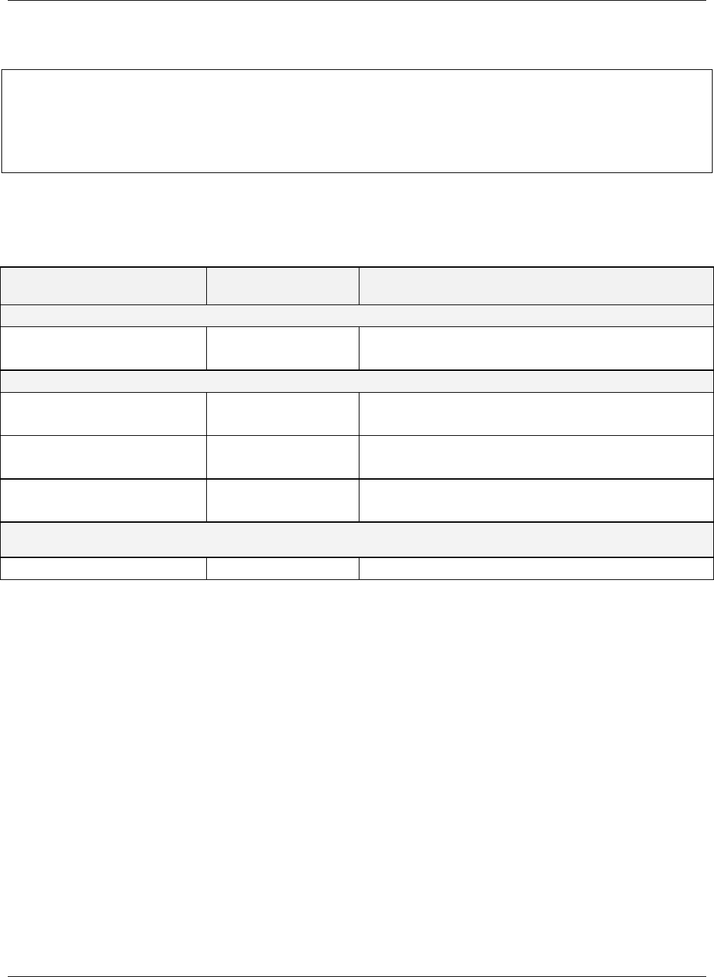
Table A-7: Signal I/O Definitions Deleted from M102 Software Revision A.2
SIGNAL NAME BIT OR CHANNEL
NUMBER
DESCRIPTION
Control inputs, U11, J1004, pins 1–6 = bits 0–5, default I/O address 321 hex
EXT_LOW_SPAN 2 0 = go into low span calibration
1 = exit low span calibration
Relay board digital output (PCF8575), default I
2
C address 44 hex
CONV_HEATER 2 0 = converter cell heater on
1 = off
LOW_SPAN_VALVE 8 0 = let low span gas in
1 = let sample gas in
ZERO_VALVE 9 0 = let zero gas in
1 = let sample gas in
Rear board primary MUX analog inputs
VACUUM_PRESSURE 10 Vacuum pressure
A-8 05515 Rev A.2