


M102E/M501 TRS M102E OPERATING INSTRUCTIONS
(Addendum to M101E Manual - P/N 04740 Rev A)
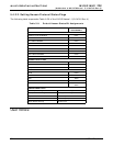
5.2.2. M102E Test Channel Output
The following table supercedes Table 6-14 of the M101E Manual - P/N 04740 Rev A
Table 5-3: Test Parameters Available for Analog Output A4
TEST CHANNEL TEST PARAMETER RANGE
1
NONE Test channel is turned off
PMT READING 0-5000 mV
UV READING 0-5000 mV
SAMPLE PRESSURE 0-40 in-Hg-A
SAMPLE FLOW 0-1000 cm³/min
RCELL TEMP 0-70° C
CHASSIS TEMP 0-70° C
IZS TEMP 0-70° C
PMT TEMP 0-50° C
CHASSIS TEMP 0-70° C
HVPS VOLTAGE 0-5000 V
1
This refers to the voltage range of the parameter and
not the output signal of the test channel.
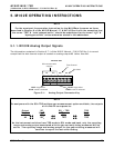
Once a TEST function is selected, the instrument begins to report a signal on the A36 output and
adds TEST= to the list of test functions viewable on the display (just before the TIME display).
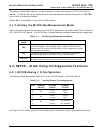
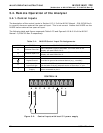
5.3. SETUP – COMM: Setting Up the M102E’s
Communication Ports
5.3.1. M102E ID Code
The default ID code for all M102E analyzers is 102.
To edit the instrument’s ID code, see Section 6.10.1 of the M101E Manual - P/N 04740 Rev A.
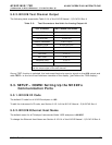
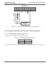
5.3.2. M102E Ethernet Host Name
The default name for all Teledyne Instruments Model 102E analyzers is M102E.
To change the Ethernet Host Name see Section 6.10.6.4 of the M101E Manual - P/N 04740 Rev A.
05514 Rev A1 27