M102E OPERATING INSTRUCTIONS M102E/M501 TRS
(Addendum to M101E Manual - P/N 04740 Rev A)
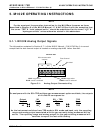
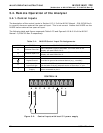
The output, labeled A3 is special. It can be set by the user (see Section 6.9.10 of the M101E
Manual - P/N 04740 Rev A) to output many of the parameters accessible through the <TST TST>
keys of the units Sample Display.
Output A4 is not available on the Model 102E Analyzer.
5.1.2. Setting the M102E Gas Measurement Mode
Setting the gas measurement mode on the M102E is identical to the method described in Sections
6.8.1 of the M101E Manual - P/N 04740 Rev A except that the available measurement ranges are:
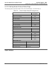
Table 5-1 M102E gas Measurement Modes
GAS
MODE
DESCRIPTION
TRS
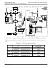
The sample gas stream is stripped of any ambient SO
2
by a special
chemical scrubber, then passed through a catalytic converter that
changes the TRS present into SO
2
which is then measured using the
UV Fluorescence method
SO
2
The sample gas stream bypasses the SO
2
Scrubber and catalytic
converter allowing the only ambient SO
2
to be measured.
TRS –SO
2
The switching valve alternates the gas stream between the two paths
at regular intervals allowing the instrument to measure both gases.
5.2. SETUP – DIAG: Using the Diagnostics Functions
5.2.1. M102E Analog I/O Configuration
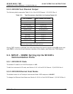
The following table supercedes Table 6-11 of the M101E Manual - P/N 04740 Rev A
Table 5-2: Analog Output Pin Assignments
PIN ANALOG
OUTPUT
VOLTAGE
SIGNAL
CURRENT
SIGNAL
1 V Out I Out +
2
A1
Ground I Out -
3 V Out I Out +
4
A2
Ground I Out -
5 V Out not available
6
A3
Ground not available
7-8
A3
Not Used Not Used
See Figure 3-4 for a the location of the analog output connector on the instruments rear panel.
26 05514 Rev A1


