


M102E/M501 TRS OPTIONAL HARDWARE AND SOFTWARE
(Addendum to M101E Manual - P/N 04740 Rev A)
4. OPTIONAL HARDWARE AND SOFTWARE
This section includes descriptions of the hardware and software options available for the Model
102E analyzer and M501-TRS converter that are different from or not included in Chapter 5 of the
M101E Manual - P/N 04740 Rev A. For all other available options see that document.
For assistance with ordering these options please contact the sales department of Teledyne
Instruments at:
TOLL-FREE: 800-324-5190
TEL: +1 858-657-9800
FAX: +1 858-657-9816
E-MAIL: apisales@teledyne.com
WEB SITE: http://www.teledyne-api.com
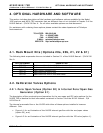
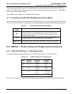
4.1. Rack Mount Kits (Options 20a, 20b, 21, 22 & 81)
The following table supercedes the one included in Section 5.1 of the M101E Manual - P/N 04740
Rev A.
OPTION NUMBER DESCRIPTION
OPT 20A Rack mount brackets with 26 in. chassis slides.
OPT 20B Rack mount brackets with 24 in. chassis slides.
OPT 21 Rack mount brackets only
OPT 22 Rack Mount for M501-TRS
OPT 81 Rack Mount for M501-TRS with slides
4.2. Calibration Valves Options
4.2.1. Zero/Span Valves (Option 50) & Internal Zero/Span Gas
Generator (Option 51)
The description of the construction and operation for the zero span and IZS valve options for the
M102E TRS is identical to that information contained in Section 5.4of the M101E Manual - P/N
04740 Rev A.
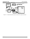
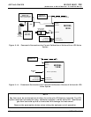
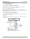
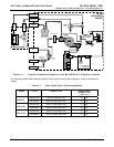
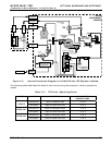
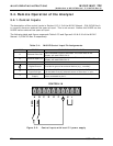
The internal pneumatic flow or the M102E with either of these options installed is however
different. See:
• Figure 4-1 for an illustration of the M102E internal gas flow with the zero/span valves
(option 50), and;
• Figure 4-2 for an illustration of the M102E internal gas flow with the IZS valve (option 1).
05514 Rev A1 21