


DCP200 Profile Controller & Recorder - Product Manual
51-52-25-150, Issue 1 – April 2009 Modbus Parameters Page 111
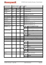
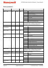
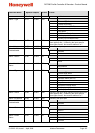
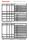
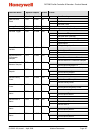
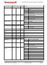
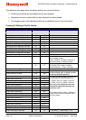
Parameter Name
Modbus Address
Access
Values
(Dec)
(Hex)
12 Event 4
13 Event 5
14 Any Event
15 Manual Control
16 Profile Running
17 Profile Ended
Backlight Colour 7668 0x1DF4 R/W
Value
Backlight Col
our
0 Green to Red on Alarm
1 Red to Green on Alarm
2 Permanent Green
3 Permanent Red
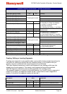
Display Language 7675 0x1DFB R/W
Value
Language
0 Main Display Language
1 Alternate Display Language
Display Contrast 7676 0x1DFC R/W 0 to 127
Invert Display 7677 0x1DFD R/W
Value
Invert Display
0 Normal Display
1 Inverted Display
Setup Lock Code 7678 0x1DFE R/W 1 to 9999. Default is 10
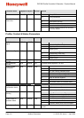
Configuration Lock
Code
7679 0x1DFF R/W 1 to 9999. Default is 10
Tuning Lock Code 7680 0x1E00 R/W 1 to 9999. Default is 10
Supervisor Lock
Code
7681 0x1E01 R/W 1 to 9999. Default is 10
Profiler Lock Code 7682 0x1E02 R/W 1 to 9999. Default is 10
USB Lock Code 7683 0x1E03 R/W 1 to 9999. Default is 10
Recorder Lock Code 7684 0x1E04 R/W 1 to 9999. Default is 10
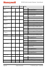
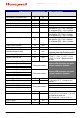
Read Only
Operation Mode
7685 0x1E05 R/W
Value
Read Only Operation Mode
0 Operation Mode Read/Write
1 Operation Mode Read Only
Bar Graph Format 7686 0x1E06 R/W
Value
Bar Graph Format
0 Power Output
1 Control Deviation
2 % Memory Remaining
Trend View Sample
Interval
9000 0x2328 R/W
Value
Trend Sample Interval
0 Every Second
1 Every 2 Seconds
2 Every 5 Seconds
3 Every 10 Seconds
4 Every 15 Seconds
5 Every 30 Seconds
6 Every Minute
7 Every 2 Minutes
8 Every 5 Minutes
9 Every 10 Minutes