


DCP200 Profile Controller & Recorder - Product Manual
51-52-25-150, Issue 1 – April 2009 Glossary Page 157
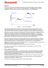
Retransmit Output n Scale Minimum
Scales a linear output module in slot n if it has been selected to retransmit the PV or SP.
Retransmit Scale Minimum defines the value of the process variable, or setpoint, at which
the output will be at its minimum value. E.g. for a 0 to 5V output, it is the PV or SP value
corresponding to 0V. If this parameter is set to a value greater than that for Retransmit n
Output Scale Maximum, the relationship between the process variable/setpoint value and the
retransmission output is reversed so that higher PV/SP values give a lower output level.
Settings = -1999 to 9999 Default value = Scale Range Lower Limit.
Also refer to: Process Variable, Retransmit Output, Retransmit Output n Scale Maximum,
Scale Range Lower Limit and Setpoint.
Reset To Defaults
This Configuration sub-menu selection returns all of the instruments settings back to their
factory defaults. It should be used with great care, as the action cannot be undone. A reset is
followed automatically by the Setup Wizard. Users must use this wizard and/or configuration
menus to set all of the parameters to the correct values for the intended application.
Also refer to: Configuration Menu, and Setup Wizard
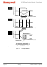
Reverse Acting Control
Reverse control action is required for applications where the primary control output will be
used to force the process variable up towards the setpoint. A typical application is a furnace.
When the control action is selected as reverse acting, primary proportional control outputs
decrease the correcting variable as the process variable increases within the proportional
band, and primary On-Off outputs turn off when the process variable exceeds the setpoint.
The control action of a secondary output is always the opposite of the primary output.
Also refer to: Control Action, Control Type, Correcting Variable, Direct Acting Control, On-Off
Control and Proportional Control.
RS485
RS485 (also known as EIA-485) is two-wire, half-duplex, multi-drop serial communications
connection. RS485 only defines the physical layer electrical specification, not the protocol
that is transmitted across it. It uses differential signals (the voltage difference between the
wires) to convey data. One polarity indicates a logic 1, the reverse polarity indicates logic 0.
The applied voltages can be between +12 V and -7 volts, but the difference of potential must
be > 0.2 volts for valid operation. RS485 can span distances up to 1200 metres using
inexpensive twisted pair wires. Data speeds can be as high as 35 Mbit/s over 10 m and 100
kbit/s at 1200 m.
It is recommended that the wires be connected as series of point-to-point (multi-dropped)
nodes (not in a star or ring format), with 120ohm termination resistors connected across the
wires at the two ends of the network. Without termination resistors, reflections of the signals
can cause data corruption, and electrical noise sensitivity is increased. The master device
should normally provide powered resistors, to bias the wires to known voltages when they
are not being driven by any device. Without biasing resistors, the data lines float and noise
can be interpreted as data when actually all devices are silent.
Converters between RS485 and other formats are available to allow computers to
communicate with remote devices. Repeaters can also be used to extend the distance
and/or number of nodes on a network.
Also refer to: Modbus RTU, and Serial Communications