


DCP200 Profile Controller & Recorder - Product Manual
51-52-25-150, Issue 1 – April 2009 Configuration & Use Page 49
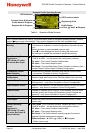
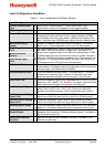
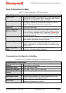
Input Configuration Sub-Menu
Table 9. Input Configuration Sub-Menu Screens
Input Configuration
:
Process Variable Input
Type
w From various Thermocouple, RTD and Linear inputs. - see
specifications section for full details of input types available.
Engineering Units w
Select display units from: °C; °F; °K; bar; %; %RH; pH; psi or none.
Decimal Point Position w
Sets the maximum display resolution to 0; 1; 2 or 3 decimal places.
Temperature inputs are limited to 0 or 1 place. Numbers >99.999
never display more than 2 dec places, >999.99 never display more
than 1 dec place and >99999 always display without a decimal place.
Multi-Point Scaling
Enable
Enables or disables Linear Input Multi-Point Scaling. This feature
allows up to 15 point linearization of mA or V DC input signals.
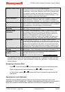
Scale Range Lower
Limit
w
For Temperature inputs, Upper & Lower Limits set the usable span.
Min span = 100 units, max span = range limits - see specs. For
Linear inputs, Upper & Lower Limits define the values shown (-1999
to 9999) when input is at minimum and maximum values. Min span =
100 units. If Multi-Point Scaling is enabled, up to 15 breakpoints* can
scale input vs. displayed value between the linear input scale limits.
*A breakpoint set at 100% input ends the sequence.
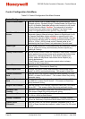
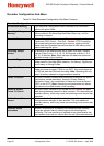
Multi-Point Scale
Point(s)
Scale Range Upper
Limit
w
CJC Enable/Disable
Enables/disables internal Thermocouple Cold Junction
Compensation. If disabled, external compensation will be required for
thermocouples. The default value is Enabled.
Process Variable Offset
Trims the measured process value. +Ve values add to, –Ve values
subtract from measured input. Caution: A value other than zero
alters the apparent calibration of the instrument. Use with care!
Input Filter Time
Removes unwanted signal noise. Adjustable from 0.0 (OFF) to 100.0
seconds or OFF (default = 2s). Caution: Too large a value will cause
slow response to changes in the process. Use with care!
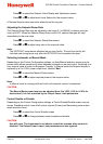
Auxiliary Input n Type w
Sets the type of signal to be connected to the auxiliary inputs (if
fitted). From: 0-10V; 2-10V; 0-5V; 1-5V, 0-20mA or 4-20mA DC.
Auxiliary input B also supports >2K Potentiometer and 0-100mV.
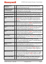
Auxiliary Input n Scaling
Lower Limit
w
Scales the displayed a value (-9999 to 10000) when an auxiliary
input is at or below it’s lower limit (e.g. 4mA for a 4-20mA signal).
Auxiliary Input n Scaling
Upper Limit
w
Scales the displayed a value (-9999 to 10000) when an auxiliary
input is at or above it’s lower limit (e.g. 20mA for a 4-20mA signal).
Auxiliary Input n Offset
Trims the displayed a value for auxiliary input A or B. +Ve values are
added to, –Ve values subtracted from the measured auxiliary input.
Calibration Reminder
Enable/Disable
Enables or disables the display of Calibration Reminder at start-up
(repeated daily thereafter), if the due date has passed – Available on
the Recorder version only
Calibration Reminder
Due Date
Sets the due date for the Calibration Reminder - Available on the
Recorder version only