


DCP200 Profile Controller & Recorder - Product Manual
Page 52 Configuration & Use 51-52-25-150, Issue 1 – April 2009
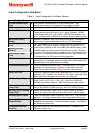
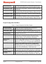
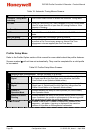
Setpoint Ramp Rate
The Setpoint Ramp Rate value (1 to 9999 display units per hour or
OFF). This ramp is applied at power-up and any setpoint changes.
Local Setpoint 1 Value w
Sets the value of Local Setpoint 1 between the Setpoint Upper and
Lower Limits.
Local Setpoint 1 Offset
A value added to the Setpoint 1 value (+ve values) or subtracted
from it (-ve values). Use when the instrument is a slave in multi-zone
applications to achieve a zone offset. Otherwise, always set to zero.
Local Setpoint 2 Value w
Sets the value of Local Setpoint 1 between the Setpoint Upper and
Lower Limits.
Local Setpoint 2 Offset
A value added to the Setpoint 2 value (+ve values) or subtracted
from it (-ve values). Use when the instrument is a slave in multi-zone
applications to achieve a zone offset. Otherwise, always set to zero.
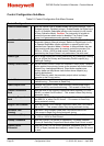
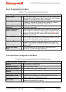
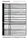
Output Configuration Sub-Menu
Table 11. Output Configuration Sub-Menu Screens
Outputs Configuration
:
No Outputs Warning
Shown if the Outputs Configuration menu is entered on an
instrument without any output modules fitted.
Linear Output n Type w
Set the desired type for any Linear Outputs fitted. From: 0-5, 0-10,
1-5, 2-10V & 0-20, 4-20mA or 0-10VDC adjustable Transmitter PSU.
Adjustable 0-10V
Transmitter PSU n
w Sets the voltage required if Linear Output n type is 0-10VDC
adjustable Transmitter PSU.
Output n Usage w
Sets the use for each output fitted. From: Primary or Secondary
Control; Alarms; Profile Events & Alarms; Retransmit Process
Variable or Setpoint. Choices offered are as appropriate for the
output type fitted (e.g. only Linear Outputs can retransmit).
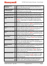
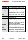
Output n Alarm
Selection
w
When an Output Usage is Alarms, this selects which alarm(s) will
cause it to change state. From Alarm 1; 2; 3; 4; 5 or a Logical OR of
alarms 1 to 2; 1 to 3; 1 to 4 or 1 to 5. Each choice is selectable with
Direct Action (on during alarm) or Reverse Action (off during alarm).
Output n Events
w
When an Output Usage is Events & Alarms, this selects which
Events(s) will cause it to change state. From: Profile Running or
Profile End; Event 1; 2; 3; 4; 5 or a Logical AND of Event n & Alarm
n. Each choice is selectable with Direct Action (on during event) or
Reverse Action (off during event). - Profiler version only
Retransmit Output n
Scale Low
w
Sets the displayed value at which a retransmission output should be
at it’s minimum level (e.g. the display value when a 4 to 20mA PV
Retransmission output will be 4mA. Adjustable from -1999 to 9999.
Retransmit Output n
Scale High
w
Sets the displayed value at which a retransmission output will be at
it’s maximum level (e.g. the display value when a 4 to 20mA PV
Retransmission output will be 20mA. Adjustable from -1999 to 9999.