


DCP200 Profile Controller & Recorder - Product Manual
Page 144 Glossary 51-52-25-150, Issue 1 – April 2009
Linear Output
A mVDC, mADC or voltage signal used to provide a proportional control or retransmit output.
Also refer to: Linear Input mVDC, mADC, Proportional Control, Retransmit Output and VDC
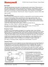
Limit Controller
A safety protection device that will shut down a process at a preset “exceed condition”. Limit
controllers work independently of the normal process controller in order to prevent possible
damage to equipment or products. A fail-safe latching relay is fitted, which cannot be reset by
the operator until the process has returned to a safe condition. Limit controllers are highly
recommended for any process that could potentially become hazardous under fault
conditions.
Also refer to: Controller and Latching Relay.
Local Setpoints
Local setpoints are target values that are stored inside the controller. These are normally
entered by from the front keypad, but can also be set via a serial communications link.
The instrument can have up to two setpoints. Local Setpoint 1 and/or an Alternative Setpoint.
The Alternative Setpoint can be chosen from Local Setpoint 2 or a remote setpoint from an
auxiliary input. One setpoint can be chosen as the active at using the Setpoint Selection.
The value of the setpoints can be adjusted between the Setpoint Upper Limit and Setpoint
Lower Limits.
Also refer to: Alternative Setpoint, Auxiliary Input, Remote Setpoint, Serial Communications,
Setpoint, Setpoint Lower Limit, Setpoint Upper Limit, and Setpoint Select.
Lock Codes
The four-digit codes required when entering the Setup Wizard, Configuration Mode, Tuning
Menu, Supervisor Mode, USB Menu, Recorder Menu and Profiler Setup Menu. These menus
can be selected from the Main Menu. The correct code must be entered to gain access. If
unlimited access is required for any of the menus, its lock can be turned off by setting the
value to OFF. Refer to the Lock Code View information in the Configuration & Use section.
Settings = 1 to 9999 or OFF. Default value = 10
Also refer to: Configuration Mode, Main Menu, Profiler Setup Menu, Recorder Menu, Setup
Wizard, Supervisor Mode, Tuning Menu and USB Menu.
Logical Combination of Alarms
Outputs for alarms may be combined to create a Logical OR situation. Possible OR
combinations are: Alarms 1 to 2; 1 to 3; 1 to 4 or 1 to 5.
Outputs for alarms & events may be combined to create a Logical AND situation. Possible
AND combinations are: Alarm 1 & Event 1; Alarm 2 & Event 2; Alarm 3 & Event 3; Alarm 4 &
Event 4; and Alarm 5 & Event 5.
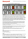
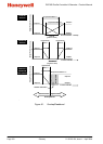
Any suitable output may be assigned as a logical output and can be configured for reverse
action or direct action. The following table explains the concept of logical OR & AND outputs.
Also refer to: Alarm Operation, Alarm Types, Output Configuration and Profile Events.