


DCP200 Profile Controller & Recorder - Product Manual
Page 24 Electrical Installation 51-52-25-150, Issue 1 – April 2009
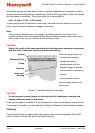
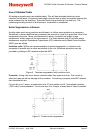
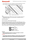
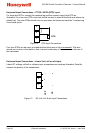
Sensor Placement (Thermocouple or RTD)
If the temperature probe is to be subjected to corrosive or abrasive conditions, it must be
protected by an appropriate thermowell. The probe must be positioned to reflect true process
temperature:
1. In a liquid media - the most agitated area
2. In air - the best circulated area
CAUTION:
The placement of probes into pipe work some distance from the heating vessel
leads to transport delay, which results in poor control.
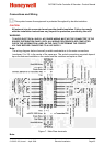
For a two wire RTD, a wire link should be used in place of the third wire (see the wiring
section for details). Two wire RTDs should only be used with lead lengths less than 3 metres.
Use of three wire RTDs is strongly recommended to reduce errors do to lead resistance.
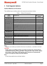
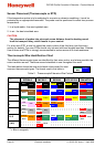
Thermocouple Wire Identification Chart
The different thermocouple types are identified by their wires colour, and where possible, the
outer insulation as well. There are several standards in use throughout the world.
The table below shows the wire and sheath colours used for most
common thermocouple types. The format used in this table is:
Table 2. Thermocouple Extension Wire Colours
Type
International
IEC584-3
USA ANSI
MC 96.1
British
BS1843
French
NFC 42-324
German
DIN 43710
J
+*
Black
Black
White
Black
Yellow
Black
Yellow
Black
Red
Blue
-
White Red Blue Black Blue
T
+
Brown
Brown
Blue
Blue
White
Blue
Yellow
Blue
Red
Brown
-
White Red Blue Blue Brown
K
+
Green
Green
Yellow
Yellow
Brown
Red
Yellow
Yellow
Red
Green
-*
White Red Blue Purple Green
N
+
Pink
Pink
Orange
Orange
Orange
Orange
-
White Red Blue
B
+
Grey
Grey
Grey
Grey
Red
Grey
-
White Red Grey
R & S
+
Orange
Orange
Black
Green
White
Green
Yellow
Green
Red
White
-
White Red Blue Green White
C (W5)
+
White
White
-
Red
Note:
* = Wire is magnetic
+ Wire
Sheath
- Wire