


DCP200 Profile Controller & Recorder - Product Manual
Page 148 Glossary 51-52-25-150, Issue 1 – April 2009
Modulating Valve
A valve that can be positioned anywhere between fully closed and fully open by means of an
incorporated motor. A typical application would be controlling temperature in a furnace
heated by gas burners. This instrument can control modulating valves that have a positioning
circuit. These require proportional (mA or VDC) control signal from a linear output, relative to
the desired valve position. PI control is used for valve control.
To directly control the valves ‘open’ and ‘close’ motor windings, a special Valve Motor Drive
(VMD) controller algorithm is required. This instrument does not currently support this type of
algorithm.
Also refer to: Linear Output, PI Control, Proportional Control and Valve Motor Drive Control.
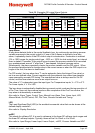
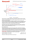
Multi-Point Scaling
If the process input is connected to a linear input signal, multi-point scaling can be enabled in
the Input Configuration sub-menu. This allows the linearization of a non-linear signal.
The Scale Range Upper & Lower Limits define the values shown when the input is at
minimum and maximum values, and up to 15 breakpoints can scale input vs. displayed value
between these limits. It is advisable to concentrate these break points in the area of the
range that has the greatest amount of non-linearity, or the area of particular interest in the
application.
Also refer to: Input Configuration, Linear Input, Process Input, Scale Range Lower Limit and
Scale Range Upper Limit.
mVDC
This stands for millivolt DC. It is used in reference to the linear DC millivolt input ranges.
Typically, these will be 0 to 50mV or 10 to 50mV
Also refer to: Auxiliary Input, Input Range, Linear Input, mADC, Process Variable and VDC
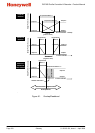
On-Off Control
When operating in On-Off mode, the control output(s) will turn on or off as the process
variable crosses the setpoint in a manner similar to a central heating thermostat. Some
oscillation of the process variable is inevitable when using On-Off control.
On-Off control can be implemented only with Relay, Triac or SSR driver outputs. On-Off
operation can be assigned to the Primary output alone (secondary output not present),
Primary and Secondary outputs or Secondary output only (with the primary Output set for
time proportional or current proportional control). On-Off Control is selected by setting the
corresponding proportional band(s) to On-Off.
Also refer to: On-Off Differential, PID, Process Variable, Primary Proportional Band,
Secondary Proportional Band, Relay, Setpoint, SSR Driver, Time Proportioning Control and
Triac.
On-Off Differential (On-Off Hysteresis)
A switching differential, centred about the setpoint, when using On-Off control. Relay ‘chatter’
can be eliminated by proper adjustment of this parameter, but too large a value may increase
process variable oscillation to unacceptable levels. On-Off differential is also know as
hysteresis or deadband.
Settings = 0.1% to 10.0% of input span. Default value = 0.5%.
Also refer to: Input Span, On-Off Control, Process Variable, Relay and Setpoint