


DCP200 Profile Controller & Recorder - Product Manual
Page 118 Modbus Parameters 51-52-25-150, Issue 1 – April 2009
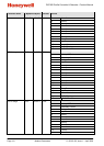
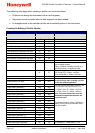
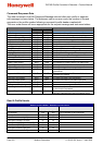
Creating, Editin
g or Inserting Segments
-
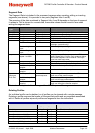
Request (
to instrument
)
Field Name
Data
Comments
(Dec)
(Hex)
Read Quantity Of Registers High 00 00
Read Quantity Of Registers Low 01 01
Write Start Address High 32 20
Write Start Address Low 06 06
Write Quantity Of Registers High 00 00
Write Quantity Of Registers Low 11 or 12 0B or 0C Create Segment (WS) = 11dec / 0x0Bhex
Insert Segment (IS) = 12dec / 0x0Chex
Edit A Segment (ES) = 12dec / 0x0Chex
Byte Count 22 or 24 16 or 18 Create Segment (WS) = 22dec / 0x16hex
Insert Segment (IS) = 24dec / 0x18hex
Edit A Segment (ES) = 24dec / 0x18hex
Command Code High Byte 87, 73 or
69
57 or 49 Create Segment (WS) = 87dec / 0x57hex
Insert Segment (IS) = 73dec / 0x49hex
Edit A Segment (ES) = 69dec / 0x45hex
Command Code Low Byte 83 53
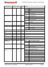
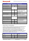
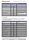
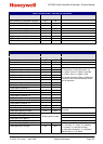
Profile Number High Byte
A/R
A/R
Profile Number Low Byte
A/R
A/R
Segment Position High Byte
A/R
A/R
Note: The Segment Position is not
included in the message when creating
a segment at the next available position.
Segment Position Low Byte
A/R
A/R
Segment Type High Byte 00 00 0 = Ramp Time, 1 = Ramp Rate,
2 = Step, 3 = Dwell, 4 = Hold, 5 = Loop
6 = Join, 7 = End, 8 = Repeat sequence
then end
Segment Type Low Byte
A/R
A/R
Segment Info A (Byte 4 - High)
Floating point number
The meaning of the data contained in
Segment Info A depends on the type of
segment it relates to. See below.
Segment Info A (Byte 3)
Segment Info A (Byte 2)
Segment Info A (Byte 1 - Low)
Segment Info B (Byte 4 - High)
Floating point number
The meaning of the data contained in
Segment Info B depends on the type of
segment it relates to. See below.
Segment Info B (Byte 3)
Segment Info B (Byte 2)
Segment Info B (Byte 1 - Low)
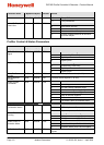
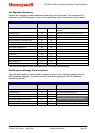
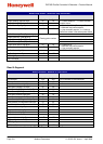
Auto Hold Type High Byte
A/R
A/R
0 = Auto-Hold Off, 1 = Hold above SP,
2 = Hold below SP,3 - Hold above and
below SP
Auto Hold Type Low Byte
A/
R
A/R
Auto Hold Value (Byte 4 - High)
Floating point number
Auto Hold Value (Byte 3)
Auto Hold Value (Byte 2)
Auto Hold Value (Byte 1 - Low)
Events High Byte 00 00 The status of the five events are defined by
the lowest 5 bits of the low byte. A bit value
of 1 signifies the event is on.
Bit 0 = event 1, bit 1 = event 2, bit 3 =
event 4 and bit 5 = event 4.
Events Low Byte
A/R
A/R
CRC High Byte
A/R
A/R
CRC Low Byte
A/R
A/R