


DCP200 Profile Controller & Recorder - Product Manual
51-52-25-150, Issue 1 – April 2009 Configuration & Use Page 51
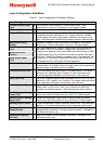
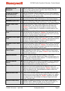
Secondary On-Off
Differential
Sets the Secondary On-Off control hysteresis (deadband) from 0.1 to
10.0% of Span (centred about setpoint), when Primary PID with
Secondary On-Off control is used.
Primary & Secondary
On-Off Differential
Sets the combined Primary & Secondary On-Off Control hysteresis
(deadband) from 0.1 to 10.0% of Span. when Primary On-Off control
and Secondary On-Off control is used.
Primary Cycle Time
Sets the Primary Power Cycle Time (0.5s to 512s). For time
proportioned Primary Relay, SSR Driver or Triac Control Outputs.
Secondary Cycle Time
Sets the Secondary Power Cycle Time (0.5s to 512s). For time
proportioned Secondary Relay, SSR Driver or Triac Control Outputs.
Primary Power Upper
Limit
Sets the Maximum Primary Output Power Limit, from 0 to 100% of
available power. This value must be higher than the lower limit.
Caution: The instrument will not be able to correctly control the
process if sufficient power isn’t available to maintain setpoint. Use
with care!
Primary Power Lower
Limit
Minimum Primary Output Power limit, from 0 to 100%. This value
must be less than the upper limit. Caution: The instrument will not
be able to correctly control the process if the lower limit is more than
required to maintain setpoint. Use with care!
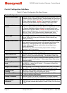
Secondary Power Upper
Limit
Maximum Secondary Output Power limit, from 0 to 100%. This value
must be higher than the lower limit. Caution: The instrument will not
be able to correctly control the process if sufficient power isn’t
available to maintain setpoint. Use with care!
Secondary Power Lower
Limit
Minimum Secondary Output Power limit, from 0 to 100%. This value
must be less than the upper limit. Caution: The instrument will not
be able to correctly control the process if the lower limit is more than
required to maintain setpoint. Use with care!
Sensor Break Pre-set
Power Output
Sets the power level applied if the process input (or active RSP) is
lost. Adjustable from 0 to 100% or -100 to +100% for Dual Control.
The default value is OFF (0% power). Caution: Use a value that will
maintain safe conditions.
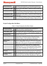
Setpoint Selection w
Sets the method to select the Active Setpoint. From: Local
Setpoint 1 only; Alternate Setpoint only; Select via Digital Input A or
B; or Operator Selectable (allows Setpoint 1 or Alternate Setpoint to
be selected from Operation Mode).
Alternate Setpoint
Source
w
Up to two setpoints can be used, Local Setpoint 1 plus an Alternate
The Alternate Setpoint can be selected from: Local Setpoint 2 or a
Remote Setpoint set via Auxiliary Input A or B.
Setpoint Upper Limit
The maximum allowable setpoint value. Adjustable within the Input
Span limits, but must be greater than the Setpoint Lower Limit.
Applies to both local and remote setpoints. Caution: Operators can
adjust the setpoint to any value between the Setpoint Upper and
Lower Limits. Use with care!
Setpoint Lower Limit
The minimum allowable setpoint value. Adjustable within the Input
Span limits, but must be less than the Setpoint Upper Limit. Applies
to both local and remote setpoints. Caution: Operators can adjust
the setpoint to any value between the Setpoint Upper and Lower
Limits. Use with care!
Setpoint Ramp Editing
Enables or disables the changing of the Setpoint Ramp Rate in
Operation Mode – Note: this does not turn off an active ramp. To
turn of an active ramp, set the Setpoint Ramp Rate to OFF.