


DCP200 Profile Controller & Recorder - Product Manual
Page 140 Glossary 51-52-25-150, Issue 1 – April 2009
CPU
This stands for Central Processing Unit and refers to the onboard microprocessor that
controls the measurement, control, alarm and display functions of the instrument.
Current Proportioning Control
Current proportioning control is used to produce the correcting variable on units with linear
output(s). It provides 4 to 20mA, 0-20mA, 0 to 5V, 0 to 10V or 2 - 10V DC for proportional
control, PI, PD or PID control modes. On-Off control cannot be used with linear outputs.
Also refer to: Correcting Variable, Linear Output, On-Off Control, PD, PI, PID, Proportional
Control, and Time Proportional Control.
Custom Display Mode
The user can copy up to 50 Configuration Menu parameters into Operation Mode using the
PC software. It the Custom Display in enabled in the Display Configuration sub-menu, these
screens follow the normal Operation Mode screens. In this mode these screens are not pass-
code protected.
Also refer to: Control Configuration, Display Configuration and Operation Mode
Cycle Time
For time proportioning outputs, the cycle time is used to define the time over which the
controller averages the ON vs. OFF time, in order to provide the required correcting variable.
Each Time-Proportioning output has its own adjustable cycle time. Shorter cycle times give
better control, but at the expense of reduce life when used with electromechanical control
devices (e.g. relays or solenoid valves). There are separate cycle times for the Primary and
Secondary control outputs
Settings = 0.5 to 512 seconds Default value = 32 secs.
Also refer to: Correcting Variable, PID, Primary Proportional Band, Proportional Control,
Relay, Secondary Proportional Band, Solenoid Valve and Time Proportioning.
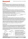
Data Recorder
The Data Recorder option can record the process value, setpoint, alarms and events over
time. Recordings can be transferred to a USB memory stick or via the serial communications
options. This option includes a USB Interface and a battery backed-up Real Time Clock.
Refer to the Data Recorder Option section of this manual for more details.
Also refer to: Recorder Configuration.
Deadband
- Refer to Overlap/Deadband.
Derivative Action
The Derivative Time Constant defines how the control action responds to the rate of change
in the process variable. The power is decreased if the PV is rising, or increased if the PV is
falling. This parameter is not available if primary control output is set to On-Off, and it is
normally set to OFF in modulating value applications as it can cause premature wear due to
constant small adjustments to the valve position.
Settings = OFF or 0 seconds to 99 minutes 59 seconds Default value = 01.15.
Also refer to: Modulating Valve, On-Off Control, PD Control, PI Control, PID, Process
Variable, Tuning and Valve Motor Drive Control.