


DCP200 Profile Controller & Recorder - Product Manual
Page 138 Glossary 51-52-25-150, Issue 1 – April 2009
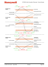
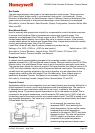
As the jacket temperature rises, the slave’s heater output falls. The product temperature also
rises at a rate dependant on the transfer lag between the jacket and product. This causes the
master’s PID output to decrease, reducing the ‘jacket’ setpoint on the slave, effectively
reducing the output to the heater. This continues until the system becomes balanced.
When tuning a cascade system, first set the master to manual mode. Tune the slave
controller using proportional control only (I & D are not normally required) then return the
master to automatic PID mode before tuning the master. The result is quicker, smoother
control with minimum overshoot and the ability to cope with load changes, whilst keeping the
jacket temperature within acceptable tolerances.
Also refer to: Auxiliary Input, Auxiliary Input Lower Limit, Auxiliary Input Upper Limit,
Derivative Action, Integral Action, mADC, Manual Mode, Master & Slave, Proportional
Control, PID, Remote Setpoint, Remote Setpoint Lower Limit, Remote Setpoint Upper Limit,
Setpoint, Setpoint Select, Tuning and VDC.
Clock Configuration
A sub-menu of Configuration Mode used to adjust the parameters that relate to the settings
for the Real Time Clock fitted with the data recorder option (Date, time, day of week and date
format).
Also refer to: Data Recorder and Configuration Mode
Communications Write Enable
Enables/disables the changing of parameter values via the Serial Communications link, if a
communication option such as Modbus RTU (RS485) or Modbus TCP (Ethernet) is installed.
When disabled, all communications are read-only.
Settings = Read Only or Read/Write. Default setting = Enabled (read/write).
Also refer to: Ethernet, Modbus RTU, Modbus TCP, RS485 and Serial Communications
Configuration Menu
A selection of sub-menus from which the user can adjust the major instrument settings.
There are sub-menus for the Inputs, Control, Outputs, Alarms, Communications, Recorder,
Clock, Display and Lock Codes. Configuration Mode is entered from the Main Menu. An
unlock code is required to access this mode.
Refer to the Configuration Menu information in the Configuration & Use section.
Also refer to: Alarm Configuration, Lock Codes, Clock Configuration, Control Configuration,
Display Configuration, Input Configuration, Main Menu, Output Configuration, Recorder
Configuration, Serial Communications Configuration
Contactor
- Refer to Relay
Control Configuration
A sub-menu of Configuration Mode used to adjust the parameters that relate to the control of
the process. (Enabling control, auto/manual mode, control type and action, PID tuning terms,
power limits, sensor break action, local setpoint values, setpoint ramp rates and setpoint
selection).
Also refer to: Configuration Mode, Control Action, Control Enable, Local Setpoints, Manual
Mode, PID, Power Limits, Sensor Break Pre-Set Power, Setpoint Ramping, Setpoint
Selection and Tuning