


DCP200 Profile Controller & Recorder - Product Manual
Page 156 Glossary 51-52-25-150, Issue 1 – April 2009
Recorder Option
- Refer to Data Recorder.
Recorder Menu
If the Data Recorder is fitted, a Recorder Menu is added to the Main Menu. This is used to
control the recording (start, stop, delete recordings etc) and to show the recorder status. This
menu is protected by a lock code.
Refer to the Recorder Menu information in the Configuration & Use section.
Also refer to: Lock Codes, Main Menu and Data Recorder
Relay
An electromechanical switch operated by a solenoid coil. Relays are commonly fitted as
internal, time proportioning controller outputs. The limited current capacity and switching
cycles of internal relays means that they are usually connected to larger external slave
relays/contactors which are capable of switching much larger currents and are easily
replaced once worn out. A suitably rated RC snubber should be connected to relays to
protect nearby equipment from the effects of noise generated as they switch (refer to the
Noise Suppression details in the Electrical Installation section).
Also refer to: Current Proportioning Control, Latching Relay, SSR Driver, Time Proportioning
Control and Triac
Remote Setpoint (RSP)
If the alternative setpoint type is selected to be a remote setpoint, and the selected setpoint
is the alternative setpoint, an Auxiliary Input value is used to adjust the controller setpoint.
The auxiliary linear input, is given a VDC or mADC signal, or in some cases potentiometer or
mV inputs. The Remote Setpoint value is constrained by the Setpoint Upper Limit and
Setpoint Lower Limit settings. Typical applications are Setpoint and Cascade Control Slaves.
Also refer to: Alternative Setpoint, Auxiliary Input, Auxiliary Input Lower Limit, Auxiliary Input
Type, Auxiliary Input Upper Limit, Cascade Control, Linear Input, Local Setpoints, Master &
Slave, mADC, mVDC, Setpoint and Setpoint Select, and VDC.
Retransmit Output
A linear VDC or mADC output signal, proportional to the Process Variable or Setpoint, for
use by slave controllers or external devices, such as a Chart Recorder or PLC. The output
can be scaled to transmit any portion of the input or setpoint span.
Also refer to: Input Span, Linear Output, mADC, Master & Slave, PLC, Process Variable,
Retransmit Output Scale Maximum, Retransmit Scale Minimum, Setpoint and VDC.
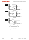
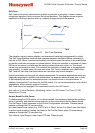
Retransmit Output n Scale Maximum
Scales a linear output module in slot n if it has been selected to retransmit the PV or SP.
Retransmit Scale Maximum defines the value of the process variable, or setpoint, at which
the output will be at its maximum value. E.g. for a 0 to 5V output, it is the PV or SP value
corresponding to 5V. If this parameter is set to a value less than that for Retransmit Output n
Scale Minimum, the relationship between the process variable/setpoint value and the
retransmission output is reversed so that higher PV/SP values give a lower output level.
Settings = -1999 to 9999 Default value = Scale Range Upper Limit.
Also refer to: Process Variable, Retransmit Output, Retransmit Output n Scale Minimum,
Scale Range Upper Limit and Setpoint.