3-3SectionConnecting to a Node
31
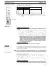
Set the communications parameters for the port to be used (port 1 or 2) with the
rotary switches, DIP switch, and CPU Bus Unit System Setup of the CVM1/CV-
series Host Link Unit (CV500-LK201).
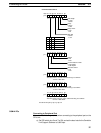
Setting the Node Number for Communications Port 2
When multiple PCs are connected to the host computer, a node number is as-
signed to each PC for identification purposes. Decimal numbers 0 to 31 can be
assigned as the node number of communications port 2. Set the tens digit with
the left switch and the ones digit with the right switch.
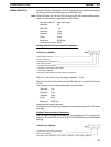
Setting Example
Node No.29x 10
0
Node No.
x 10
1
Note 1) Do not specify a node number higher than 31. Doing so results in a error and
lights the ERC2 indicator on the display panel.
2) Since the Controller Link Support Software and the Host Link Unit are al-
ways connected on the one-to-one basis, the node number can normally be
0.
3) The node number of communications port 1 is fixed at 0.
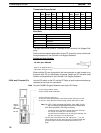
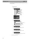
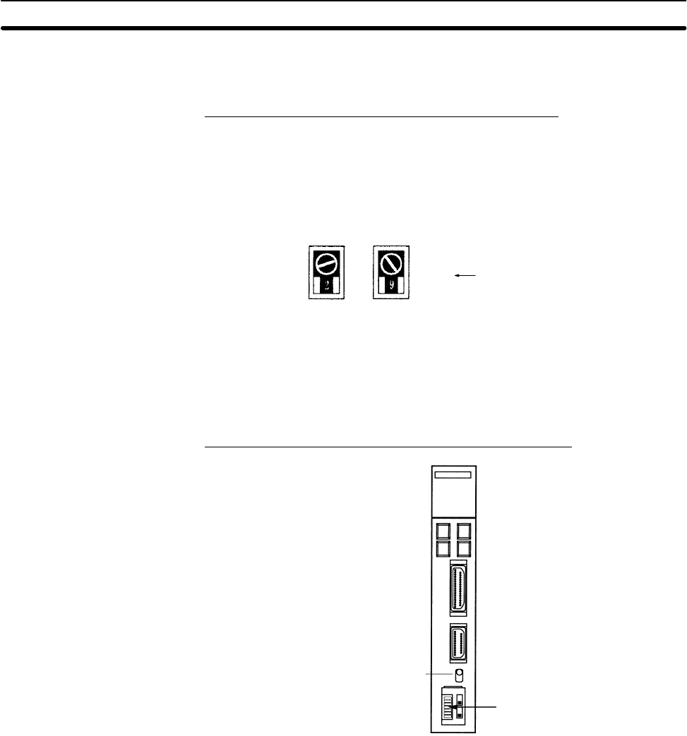
DIP Switch Settings of CVM1/CV-series Host Link Units
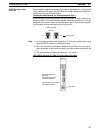
Communications port switch
(RS-232C/RS-422A)
DIP switch
Communications port 1
(RS-232C)
Communications port 2
(RS-232C/RS-422A)
CVM1/CV-series Host
Link Unit


