5-3SectionL: Data Link
56
words for areas 1 and 2.The data link area always starts from the
beginning of the specified area, and data link status cannot be
read using functions or driver call. Computers do not have a spe-
cific areas.
b) In Wired Controller Link Networks, node addresses can only be
set in the range 1 to 32. The same restriction applies to Controller
Link Networks that consist only of Optical Controller Link Units
(with CLK11 at the end of the model number), or that consist of
both Optical Controller Link Units and Optical Ring Controller Link
Units (with CLK12 at the end of the model number). Node
addresses 1 to 62 can only be used in Controller LInk Networks
that consist of Optical Ring Controller Link Units only.
c) If a start word address is specified between LR 000 and LR 199 for
a CS1-series, CVM1, or CV-series PC, it will be allocated to the
CIO1000 to CIO1199.
d) The number of DM words and the number of EM banks differ ac-
cording to the CPU Unit model used. Refer to the PC operation or
programming manual for details.
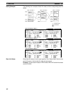
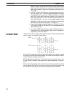
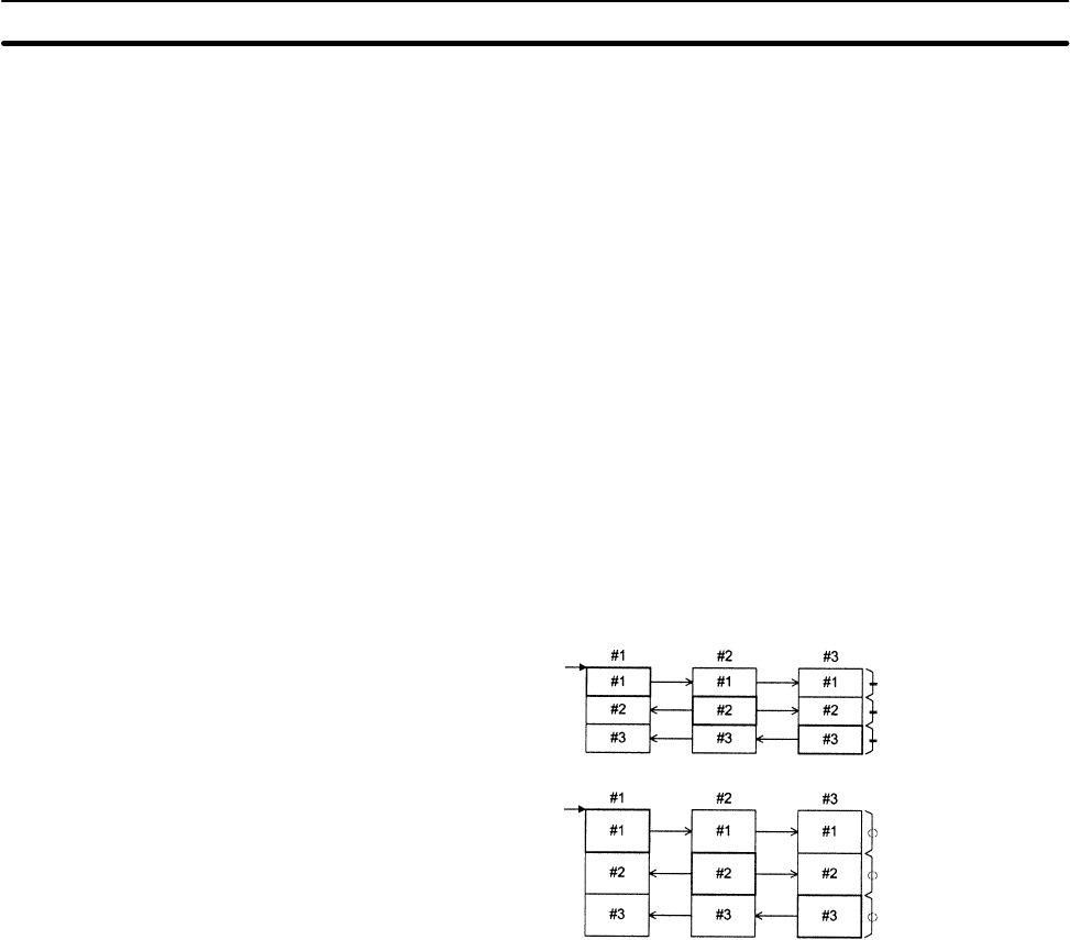
“Set All” can be used to simply create data link areas similar to automatically set
data link areas. An example is shown below.
Start word
Same size
Start word
Same size
Area 1
Area 2
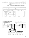
After “Set All” is performed, highly flexible data link tables can be quickly created
by changing the link start word addresses, the number of send words, and the
number of receive words for each node.
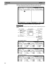
With automatically set data links, only limited areas can be used for areas 1 and
2. With “Set All,” however, data areas can be freely selected for link areas 1
and 2.
With automatically set data links, data links must use the automatically created
data link areas. With “Set All,” the link start word, the number of send words, and
the number of receive words can be freely changed for each node later.
Creating Simple Data
Link Areas — Set All


