


21
Controls and Displays 02
02Controls and Displays
English
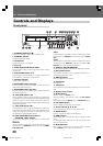
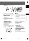
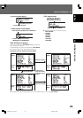
Rear panel
75
1 2 3 4 5 6
1817161514131211
7 8 109
1 Power cord connector (AC IN)
2 Extend Terminal connector (EXT TERMINAL)
External switches can be connected to control the DVD-V8000
(page 89).
The connector can also be used as an RS-232C interface.
3 RS-232C interface connector
A computer can be connected to allow serial-port control of
the DVD-V8000 (page 84).
4 External sync signal input connector
(EXT SYNC IN)
Input/output terminals for external sync signals (page 80).
5 External sync signal terminator switch
(75Ω ON/OFF)
This switch is used to terminate an external sync signal.
(Default position: ON)
6 Coaxial digital audio output jack
(DIGITAL AUDIO OUT COAXIAL)
Outputs coaxial digital audio signals.
7 Optical digital audio output connector
(DIGITAL AUDIO OUT OPTICAL)
Outputs optical digital audio signals.
8 Audio output jacks (AUDIO OUT L, R)
Outputs analog audio signals.
9 AUDIO IN LEVEL adjustment dial
Use to adjust the level of audio signals input to the audio
input connectors. Factory default setting is at the center po-
sition; rotating the dial to the left (MIN) side reduces the sound
level, and rotating the dial to the right (MAX) side increases
the sound level.
Important
¶ The DVD-V8000 is provided with video and audio input
connectors, and supports the use of 1 Vp-p composite
video signals and 2 Vrms (0 dBfs) analog audio signals. If
signals are input with levels greatly exceeding these val-
ues, the through output signals may generate video noise
and audio distortion.
¶ The range of adjustment possible with the external audio
input level dial is from –∞ to +6 dB. However, it should be
used only to the degree that the through audio output sig-
nal level is 2 Vrms (0 dBfs) or less. Allowing signal levels
greater than 2 Vrms may cause sound distortion.
10 AUDIO IN jacks (L, R)
Outputs analog audio signals (page 77).
11 USB port (MOUSE/MEMORY)
Can be used to connect a USB mouse/pen tablet, or USB
memory device.
12 DVI output connector (DVI-D)
Outputs DVI video.
13 TV system switch
(TV SYSTEM NTSC/PAL/AUTO)
When playing video discs, this control changes the output
television signal format to match the signal format recorded
on the disc. (Default: AUTO)
14 Component video output jacks
(COMPONENT VIDEO OUT, Y, P
B, PR)
Outputs component video signals.
15 S-VIDEO output terminal (S-VIDEO OUT)
Outputs S-video signals.
16 Composite video output jack (VIDEO OUT)
Outputs composite video signals (page 26).
17 Monitor video output jack
(MONITOR VIDEO OUT)
Outputs monitor video signals.
18 Composite video input jack (VIDEO IN)
Use to input composite video signals from an external source
(page 77).
DRE1031C_En_020-027 06.8.25, 8:59 AM21