


89
Additional Materials 09
09
Additional Materials
English
1. Introduction
The terminals SW1 to SW8 for the rear panel’s EXT TERMI-
NAL connector each has +3.3 V pull-up voltage. Functions
are produced as a result of the combinations possible based
on whether each terminal is shorted to GND or not. (See page
84 for pin assignments).
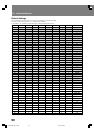
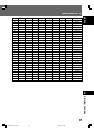
The combination of input ports for SW1 to SW8 result in a
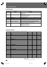
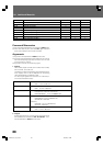
maximum of 82 settable switches. For the combinations and
their supported functions, see “Default settings” (pages 90
to 91).
Also, the relationship of SW combinations and their supported
functions is not fixed; the function setting can be changed
for some combinations in the ADV. SETUP menu (page 63).
2. SW and functions (commands)
The Extend Terminal functions can be divided broadly into
three types:
1 Functions that call command stack [GROUP]
STACK GROUP 1 to 27 are keys used to call and execute
previously recorded Command Stack.
2 Functions with same function as remote control unit
buttons
MENU, TOP MENU, », «, |, \, ENTER, RETURN,
PLAY, STOP, PAUSE, STEP FWD/REV, SCAN FWD/REV,
SKIP FWD/REV, DISPLAY, RECALL, MEMORY, REPEAT,
REPEAT A-B, AUDIO, ANGLE, SUBTITLE, SETUP, 0 to 9,
CLEAR, TITLE/CHP/FRM/TIME
Extend Terminal Specifications
However, SCAN FWD/REV operates differently from the re-
mote control unit, since it lacks the scan lock function (fast
forward/reverse scan is performed even if the SW is released).
3 Expanded functions from the remote control unit
• 10 to 20 (direct numeral input to 20 during selecting search
and menu item selection)
• OPEN/CLOSE
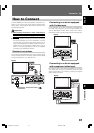
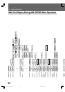
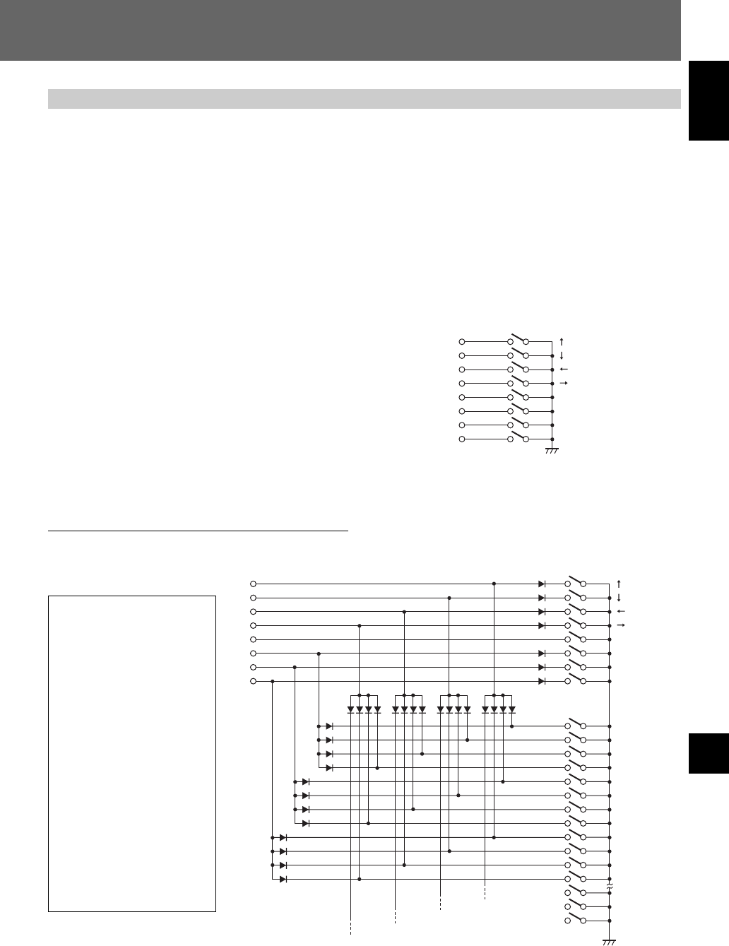
3. Connections to controller (SW interface)
The following is an example of connections with controller:
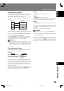
(1)Simple example without using diode matrix
In this case, the number of switches that can be allocated
(usable functions) is reduced.
SW1
SW2
SW3
SW4
SW5
ENTER
SW6
STACK GROUP 1
SW7
STACK GROUP 2
SW8
STACK GROUP 3
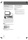
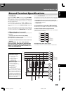
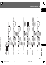
(2)Example using diode matrix (partial)
In this case, a maximum of 82 switches can be allocated.
SW1
SW2
SW3
SW4
SW5
ENTER
SW6
STACK GROUP 1
SW7
STACK GROUP 2
SW8 STACK GROUP 3
1
2
3
4
5
6
7
8
9
10
11
12
Specifications of switches used
in connection example:
Connection resistance:
1 Ω or less
Insulation resistance:
1 MΩ or more
Non-lock type
Specifications of diodes used in
connection example:
Forward voltage (VF):
0.7 V or less (IF 1 mA)
Surge current:
100 mA or less
Forward current:
10 mA or less (VR=10 V)
When synchronizing a player
with frame-unit accuracy, the
use of serial command control
is necessary. The parallel con-
trols and remote control unit
controls noted here cannot be
used for synchronized playback
at frame-unit accuracy.
DRE1031C_En_074-091 06.8.25, 9:16 AM89