


84
09 Additional Materials
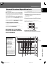
Serial Interface Specifications
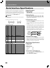
In addition to the basic operations via main unit control panel
and remote control unit, the DVD-V8000 is equipped with a
RS-232C serial control interface supporting connection to a
computer. Two types of D-Sub serial connectors are provided
(9-pin and 15-pin). The selection of one or the other of the
connectors is made via the ADV. SETUP menu.
Important
¶ The 9-Pin and 15-Pin connectors cannot be accessed si-
multaneously.
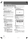
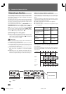
Connector pin assignments are as shown.
18
15
9
51
69
Control Functions
(a) Serial control
TxD, RxD, DTR
Serial control interface complying with RS-232C standards.
(b) Extend Terminal
SW1, SW2, SW3, SW4, SW5, SW6, SW7, SW8
Simple control of the player can be effected by connect-
ing switches to these terminals.
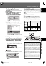
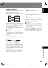
(c) External power control
The player’s power control can be effected via the inter-
face connector’s POWER pin.
Control is disabled when key-lock is set. Unset the key-
lock before attempting to use the external power control
function.
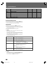
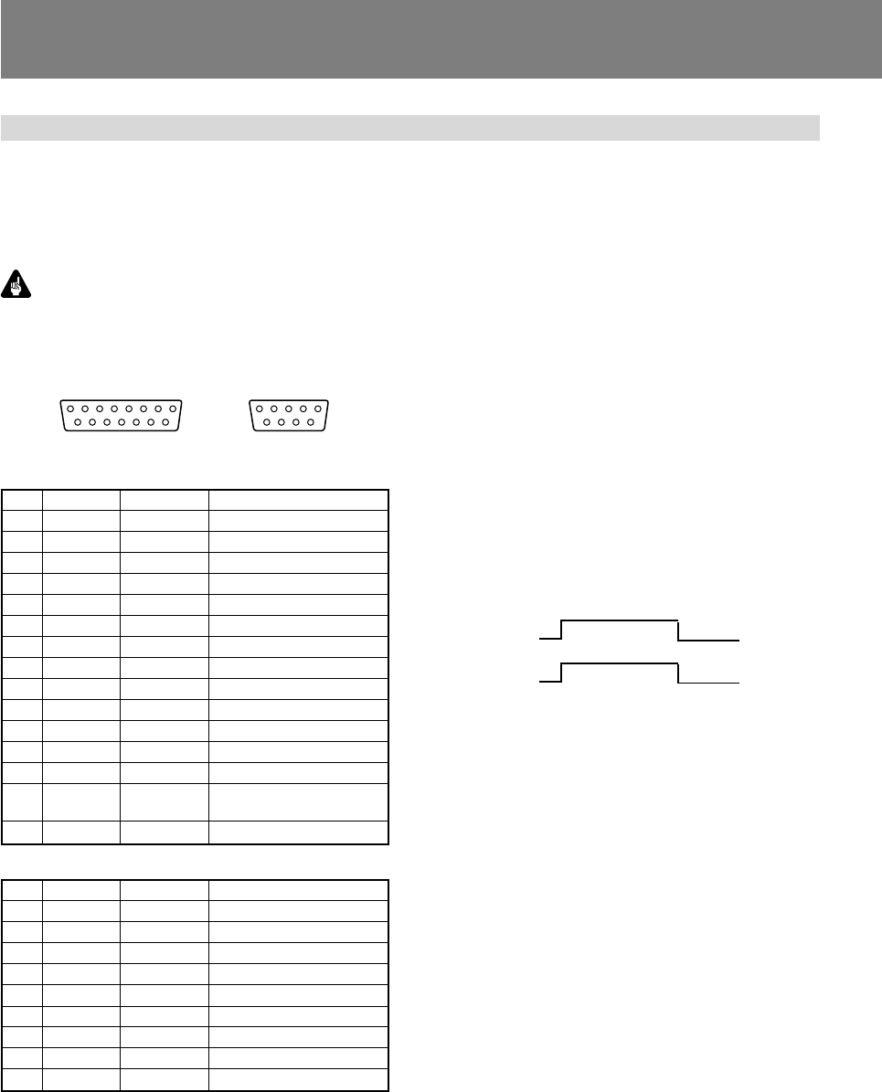
In the standby condition, when an H signal of 100 msec or
more is followed by a L signal, the power ON sequence is
performed. In the power ON condition, impression of the
same series of signals will produce the power OFF se-
quence, placing the player in the standby condition.
Terminal input voltage is ±12 V or less, with H signal level
of 4.5 V or above, and L signal of 0.5 V or below.
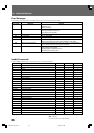
15-pin D-Sub connector
9-pin D-Sub connector
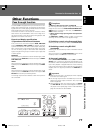
Pin #
1
2
3
4
5
6
7
8
9
Terminal
NC
RxD
TxD
DTR
GND
DSR
RTS
CTS
NC
Input/Output
--
Input
Output
Output
--
Input
Output
Input
Function
receive data
send data
enable data receiving
ground
data set ready
request to send
clear to send
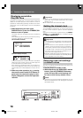
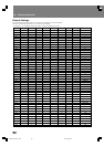
Pin #
1
2
3
4
5
6
7
8
9
10
11
12
13
14
15
Terminal
GND
TxD
RxD
DTR
POWER
SW1
SW2
SW3
SW4
SW5
SW6
SW7
SW8
DLTST
STOP_ST
Input/Output
--
Output
Input
Output
Input
Input
Input
Input
Input
Input
Input
Input
Input
Input
Output
Function
ground
send data
receive data
enable data receiving
external power control
Extend Terminal
Extend Terminal
Extend Terminal
Extend Terminal
Extend Terminal
Extend Terminal
Extend Terminal
Extend Terminal
used only for servicing
the unit — reserved
Stop Status
Standby
condition
100 ms
or more
Power ON
sequence
∞
Power ON
condition
100 ms
or more
Power OFF
sequence
∞
(d) Playback status output
The interface connector’s STOP_ST Pin can be used to
detect the player’s status (play/stop). The “L” signal is
detected during player stop, and the “H” signal during
playback. Since output collector output is used, pull-up
should be to maximum 12 volts (50 mA).
Serial Control Specifications
(1) Signal level
RS-232C level
(2) Data format
Data length: 8 bits
Stop bit: 1 bit
Parity: None
(3) Transmission speed (Baud rate)
Baud rate is selectable from 4800, 9600, 19200 (bps), set
via the ADV. SETUP menu.
Factory default setting is 4800 bps.