


Connections
02
50
En
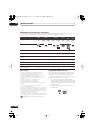
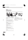
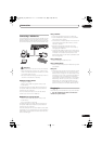
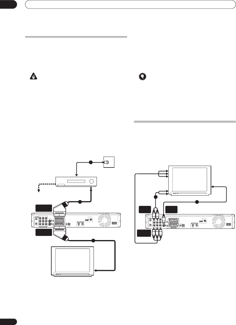
Easy connections
The setup described below is a basic setup that allows
you to watch and record TV programmes, and play discs.
Other types of connections are explained starting on the
following page.
Important
• These connections use SCART cables (not supplied).
If your TV (or VCR) does not have a SCART
connection, and you want to use the supplied audio/
video cable, see
Basic connections
on page 10.
• The
AV1 (RGB)-TV
AV connector can output ordinary
(composite), S-video or RGB video, plus stereo
analog audio. The
AV2 (INPUT 1/DECODER)
connector accepts ordinary, S-video and RGB video
input, as well as stereo analog audio. See
AV1 Out
and
AV2/L1 In
on page 140 for how to setup these
options.
• Before making or changing any rear panel
connections, make sure that all components are
switched off and unplugged from the wall outlet.
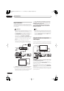
1 Connect your TV antenna to the recorder and TV.
See
Connecting a TV antenna
on page 49 for details.
• If you want to incorporate a VCR in your setup, connect
it
before
the recorder (i.e., between the antenna wall
outlet and the antenna input on the recorder).
2 Use a SCART cable (not supplied) to connect the
AV1 (RGB)-TV
AV connector on this recorder to the
SCART AV connector on your TV.
3 Use another SCART cable to connect the
AV2
(INPUT 1/DECODER)
AV connector to a SCART AV
connector on your VCR.
Tip
• This recorder has a ‘through’ function which allows
you to record a TV programme from the built-in TV
tuner in this recorder while watching a video playing
on your VCR (To use this feature when the recorder is
in standby,
Power Save
must be set to
Off
— see
Power Save
on page 137).
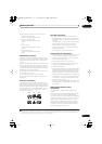
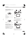
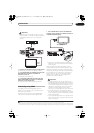
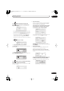
Using the S-video or component
video output
If you can’t use the SCART AV connector to connect your
TV to this recorder, there are standard audio/video output
jacks, as well as an S-video and component video output.
1 Connect the S-video or component video output
to a similar input on your TV.
For an S-video connection, use an S-video cable (not
supplied) to connect the
S-VIDEO OUTPUT
jack to an S-
video input on your TV.
For a component video connection, use a component
video cable (not supplied) to connect the
COMPONENT
VIDEO OUT
jacks to a component video input on your TV.
See also
Component Video Out
on page 139 for how to set
up the component video output for use with a progressive
scan-compatible TV.
AC IN
DIGITAL
AUDIO OUT
COAXIAL
HDMI OUT
CONTROL
G-LINK
IN
AV 1 (RGB) – TV
AV 2 (INPUT 1/DECODER)
S-VIDEO
VIDEOAUDIO
L
R
INPUT 3
COMPONENT VIDEO OUT
Y
P
B
PR
ANTENNA
IN
OUT
ANTENNA(DIGITAL)
IN
OUT
5 V
30 mA
OUTPUT
VCR
TV
Antenna/cable TV
wall outlet
1
2
3
To recorder's
antenna input
From SCART AV
connector
To SCART AV
connector
AV2 (INPUT 1/
DECODER)
AV1 (RGB) - TV
From antenna output
To antenna input
TV
AC IN
DIGITAL
AUDIO OUT
COAXIAL
HDMI OUT
CONTROL
G-LINK
IN
AV 1 (RGB) – TV
AV 2 (INPUT 1/DECODER)
S-VIDEO
VIDEO
AUDIO
L
R
INPUT 3
COMPONENT VIDEO OUT
Y
P
B
P
R
ANTENNA
IN
OUT
ANTENNA(DIGITAL)
IN
OUT
5 V
30 mA
OUTPUT
1
2
COMPONENT
VIDEO OUT
S-VIDEO
OUTPUT
AUDIO
OUTPUT
To audio input
To component video input
To video input
DVRLX60D_WV_EN.book 50 ページ 2007年4月24日 火曜日 午後7時58分