


Connections
02
51
En
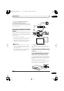
2 Connect the AUDIO OUTPUT jacks to the
corresponding audio inputs on your TV.
You can use the supplied audio/video cable, leaving the
yellow video plug disconnected. Make sure you match up
the left and right outputs with their corresponding inputs
for correct stereo sound.
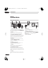
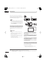
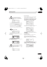
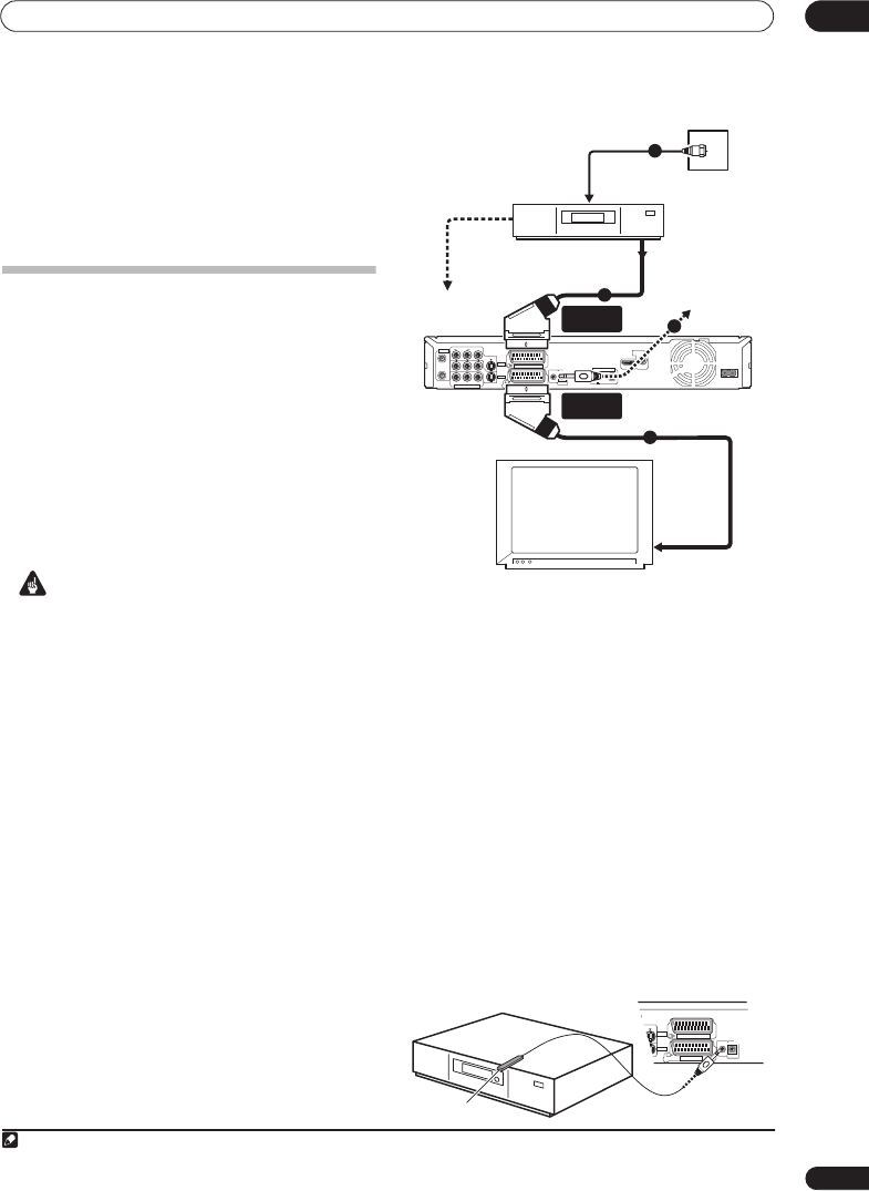
Connecting to a cable box or satellite
receiver
If you have a cable box or satellite receiver with a built-in
decoder, connect it to this recorder and your TV as shown
on this page.
1
If you are using a separate decoder box for
your cable/satellite TV, set up following the instructions
on the next page.
Using the setup on this page you can:
• Record any channel by selecting it on the cable box,
satellite receiver or digital terrestrial receiver.
• Change channels and set timer recordings on the
external receiver using the GUIDE Plus+® system
(via the G-LINK™ cable, and after setting up).
Important
• Do not connect this recorder to your TV ‘through’
your VCR, satellite receiver or other component.
Always connect each component directly to your TV
or AV amplifier/receiver.
• When using the GUIDE Plus+ system to make a
timer recording from an external receiver, make sure
that the external receiver is switched on.
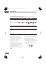
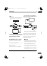
1 Connect RF antenna cables as shown.
See
Connecting a TV antenna
on page 49 for more on RF
antenna connections, including from this recorder to
your TV.
2 Use a SCART cable (not supplied) to connect the
AV1 (RGB)-TV AV connector to a SCART AV connector
on your TV.
This enables you to watch discs.
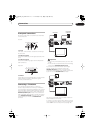
3 Use another SCART cable to connect the AV2
(INPUT 1/DECODER) AV connector to a SCART AV
connector on your cable box/satellite receiver.
This enables you to record scrambled TV channels.
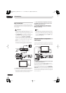
4 Plug the supplied G-LINK™ cable to the G-LINK™
jack.
This enables you to control the tuner in the external
receiver using the GUIDE Plus+® system.
Position the IR transmitter end of the G-LINK™ cable so
that the IR receiver on your cable/satellite receiver will
pick up the control signals (see diagram).
Note
1 The diagram shows SCART video connections, but you can alternatively use any of the other audio/video connections.
AC IN
DIGITAL
AUDIO OUT
COAXIAL
HDMI OUT
CONTROL
G-LINK
IN
AV 1 (RGB) – TV
AV 2 (INPUT 1/DECODER)
S-VIDEO
VIDEOAUDI O
L
R
INPUT 3
COMPONENT VIDEO OUT
Y
P
B
P
R
ANTENNA
IN
OUT
ANTENNA(DIGITAL)
IN
OUT
5 V
30 mA
OUTPUT
TV
Satellite dish/
antenna/cable TV
wall outlet
Cable/Satellite
receiver
To recorder's
antenna input
1
2
3
To SCART AV
connector
AV2 (INPUT 1/
DECODER)
AV1 (RGB) - TV
From antenna output
To antenna input
4
From SCART AV
connector
CONTROL
G-LINK
IN
AV 1 (RGB) – TV
AV 2 (INPUT 1/DECODER)
S-VIDEO
O
INPUT 3
OUTPUT
G-LINK cable
DVRLX60D_WV_EN.book 51 ページ 2007年4月24日 火曜日 午後7時58分