Appendix I Installing the Computer Interface 109
If you selected AUTO PCI during the application software installation,
WinView/WinSpec automatically put the required INF, DLL, and USB driver
file in the "Windows" directories shown below. Refer to Table 11 below for the
appropriate file names and locations.
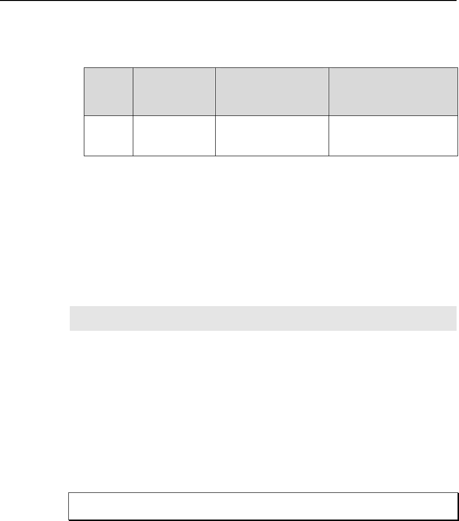
Windows
Version
USB INF Filename
Located in
"Windows"/INF
directory*
USB Properties DLL
Located in
"Windows"/System32
directory
USB Device Driver Name
Located in
"Windows"/System32/Drivers
directory
Windows
®
2000 and
XP
rsusb2k.inf (in
WINNT/INF, for
example)
apausbprop.dll (in
WINNT/System32, for
example)
apausb.sys (in
WINNT/System32/Drivers, for
example)
* The INF directory may be hidden.
Table 11. USB Driver Files and Locations
ISA Serial Card
Introduction
ISA Serial boards were available before the PCI board, now standard, or the USB 2.0
interface were developed. ISA Serial Buffer boards are still supported through version
2.5.X of the WinView/32 and WinSpec/32 application software. Version 2.6 and higher
will not support ISA.
Note: An ISA serial interface card operated in an ISA slot can support data transfer rates
as high as 1 MHz (WinView or WinSpec software ver. 1.4.3 or later).
A screwdriver may be needed to remove screws from the computer (the type varies from
computer to computer). A small, flat-bladed screwdriver is needed to connect both ends
of the serial cable.
Checking the ISA Serial Board Jumpers
Before installing an ISA Interface Board, its address should be confirmed. The factory
default address is 0A00. This address can be confirmed or changed by comparing the 8
dip switches found on the board with Figure 61. The ISA Serial Buffer board is set to
interrupt level 10 and uses DMA channels 5 and 6. The interrupt level can be changed by
the user, as long as both hardware and software are set to the same interrupt. Figure 61
shows all possible configurations. If the default DMA channels present a problem,
contact the factory for more information.
Since interrupts and DMA channels cannot be shared, make sure no other boards in your
computer use this interrupt or these DMA channels.
Installation
1. Remove the expansion slot cover on the rear panel of the I/O slot selected.
2. Insert the ISA Serial Interface card as far as possible into the appropriate ISA
socket. Then secure the Serial Buffer Board by reinstalling the expansion slot
cover screw.
3. Connect the serial cable to the 9-pin cable on the ISA Serial Buffer Board
mounting panel. The other end of the serial cable connects to the SERIAL COM
Caution


