


Appendix G Interline CCD Cameras 89
NOTSCAN
Mechanical Shutter
Acquire Readout
ClosedOpen
Exposure time
Shutter compensation
t
exp
t
c
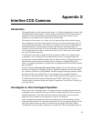
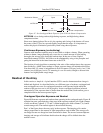
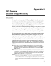
Figure 47. Non-Overlapped Mode Exposure of the CCD with Shutter Compensation
NOTSCAN is low during readout, high during exposure, and high during shutter
compensation time.
Since most shutters behave like an iris, the opening and closing of the shutter will cause
the center of the CCD to be exposed slightly longer than the edges. It is important to
realize this physical limitation, particularly when using short exposures.
Continuous Exposure (no shuttering)
Cameras with interline capability may be used with or without a shutter. When operating
without a shutter, image smearing may occur due to a small amount of light leaking
through to the storage cells during the readout time. In the case of lens-coupled
intensified cameras (ICCDs), this effect can be eliminated by using a fast phosphor and
gating the intensifier at the same frame rate as the CCD.
The fraction of total signal due to smearing is the ratio of the readout time to the exposure
time divided by ~4000. Faster readout or longer exposure times will minimize this effect.
Note that while 1% smear is insignificant in an 8-bit camera (256 gray levels), in a 12-bit
camera (over 4,000 gray levels) 1% smearing is over 40 counts, enough to obscure faint
features in a high dynamic range image.
Readout of the Array
In this section, a simple 6 × 4 pixel interline CCD is used to demonstrate how charge is
shifted and digitized. As described below, two different types of readout, overlapped and
non-overlapped can occur. In overlapped operation, each exposure begins while the
readout of the previous one is still in progress. In non-overlapped operation (selected
automatically if the exposure time is shorter than the readout time) each readout goes to
completion before the next exposure begins.
Overlapped Operation Exposure and Readout
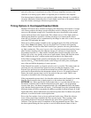
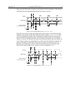
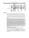
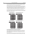
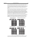
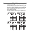
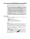
Figure 48 illustrates exposure and readout when operating in the overlapped mode. Figure 48
contains four parts, each depicting a later stage in the exposure-readout cycle. Eight columns
of cells are shown. Columns 1, 3, 5 and 7 contain imaging cells while columns 2, 4, 6 and 8
contain storage cells. The readout register is shown below the array.
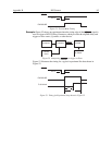
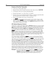
Part 1 of the figure shows the array early in the exposure. The imaging cells contain
charge proportional to the amount of light integrated on each of them. The storage cells
are empty because no charge has been transferred to them. The arrows between adjacent
imaging and storage cells indicate the direction the charge will be shifted when the
transfer occurs.