


Chapter 2 Getting Started 23
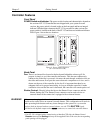
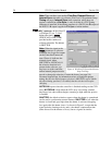
TTL IN/OUT connector: (TAXI and USB 2.0) This 25-pin connector (type
DB25) provides a programmable interface. There are eight input bits and
eight output bits that can be written to or polled to provide additional
control or functionality. For the IN lines, a bit can be set to the buffered
state, resulting in a real-time sample or it can be set to the latched state,
where the signal is maintained once set. See Appendix C for a
description of the pin assignments and refer to your software manual for
calling conventions.
AUX BNC connector: (TAXI and USB 2.0) Not currently activated.
Reserved for future use.
SERIAL COM connector: (TAXI) The cable that goes to the computer
connects to this DB9 connector. Its purpose is to provide two-way serial
communication between the controller and the computer. When
connecting this cable, it is essential that the cable connector locking
screws be tightened securely to ensure reliable operation.
If the application requires use of the optional fiber-optic data link to
increase the maximum allowable distance between the Camera and the
computer, the fiber-optic "pod" would be connected to the Serial Com
connector with a short length of cable. Then the long-distance cable
would be connected to the pod. A similar fiber-optic pod connection
would be required at the computer.
See Appendix I, Installing the Computer-Controller Interface, for detailed
information on installing and testing the TAXI serial interface link.
USB 2.0 connector: (USB 2.0) The USB cable that goes to the computer
connects to this connector. Its purpose is to provide two-way
communication between the controller and the computer.
To minimize any possible risk to system equipment, we recommend that the interface
cable (TAXI or USB) not be connected or disconnected when the system is powered.
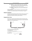
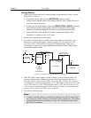
Programmable Timing Generator Module: This module should always be located
in the third slot. See Appendix B for a detailed description of the PTG and its
operation. In brief, the PTG module provides the following functions:
Ext. Trig. In: The PTG can be either internally or externally triggered as
selected in software. If external triggering is selected, the PTG will be
triggered by an externally derived trigger pulse applied to this input. The
threshold (range ±5 V), slope, coupling mode (ac or dc), and input
impedance (High or 50 Ω) are selectable in software.
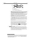
Pre. Trig. In: TTL level used only to start a bracket pulse.
T0: TTL Trigger output coincident with PI-MAX gate. This output does not need
to be connected to PI-MAX.
Timing Gen: Gate Start/Stop and Bracket signals are provided at this connector.
This output must be cabled to the PI-MAX Timing Gen connector.
Caution